POSITION TRANSMITTERS
CALIBRATION
A - 5
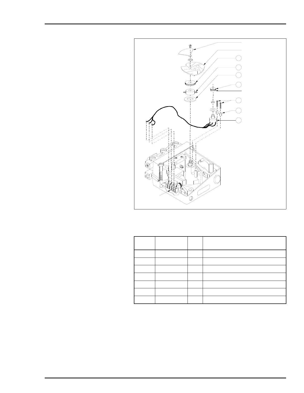
d. Tighten the set screw on the small gear hub.
NOTE: If the mesh between the large and small gears is not
tight, adjust the position of the potentiometer mounting bracket
(Fig. A-3 and Table A-1) so that backlash is eliminated.
e. Remove the ohmmeter from TB1-1 and TB1-2. Install the
cam, screw, flag, nut and washer (Fig. A-3 and Table A-1).
Po
Figure A-3. Potentiometric Position Transmitter (Exploded View)
Table A-1. Potentiometric Position Transmitter Kit 258670_1
Item
No.
Part No. Qty Description
21 6639540_2 1 Potentiometer assembly
27 193243_1 1 Large position transmitter gear
31 19734_45 1 Washer
60 5400317_1 1 Gear adapter
92 NDPAC13012 2 Threaded forming screw
95 5400268_1 1 Potentiometer mounting bracket
96 193242_1 1 Small position transmitter gear
NOTES:
1. SOME HARDWARE ITEMS HAVE
BEEN OMITTED FOR CLARITY.
2. IDENTIFIED ITEMS PERTAIN TO
THE POSITION TRANSMITTER
OPTION ONLY.
T00788A
TERMINAL
BLOCK TB1
21
95
96
31
60
27
92
POTENTIOMETER
(2000 )
Ω
SET SCREW
CAM
FLAG
MOUNTING BRACKET
SMALL GEAR
LARGE GEAR
 Loading...


