REPAIR AND REPLACEMENT
REPLACEMENT PROCEDURES
8 - 3
4. Remove the four hinge screws (Item 42) while holding the beam
assembly steady (Item 6). Remove the two screws that connect the
beam to the hinge first.
5. Remove the gain hinge spring.
6. Insert the new gain hinge spring.
NOTE: When installing the gain hinge spring, be sure it properly
seats (flush) between the steps. If the gain hinge spring hangs
up, remove and rotate the hinge 90°. Check for proper seating.
7. Insert and torque the screws to 2.6, ±0.2 Nm (23, ±2 in.-lbs) while
holding the beam assembly steady (Item 6). Insert the two screws
that secure the hinge to the housing first.
8. Transfer the positioner back to automatic operation (Section 5).
9. Perform the procedure outlined in PILOT VALVE STROKE
ADJUSTMENT.
Pilot Valve Assembly
NOTES:
1. Refer to Section 9 for pilot valve assembly kit numbers.
2. Item numbers in this procedure reference Figure 9-3 or 9-4.
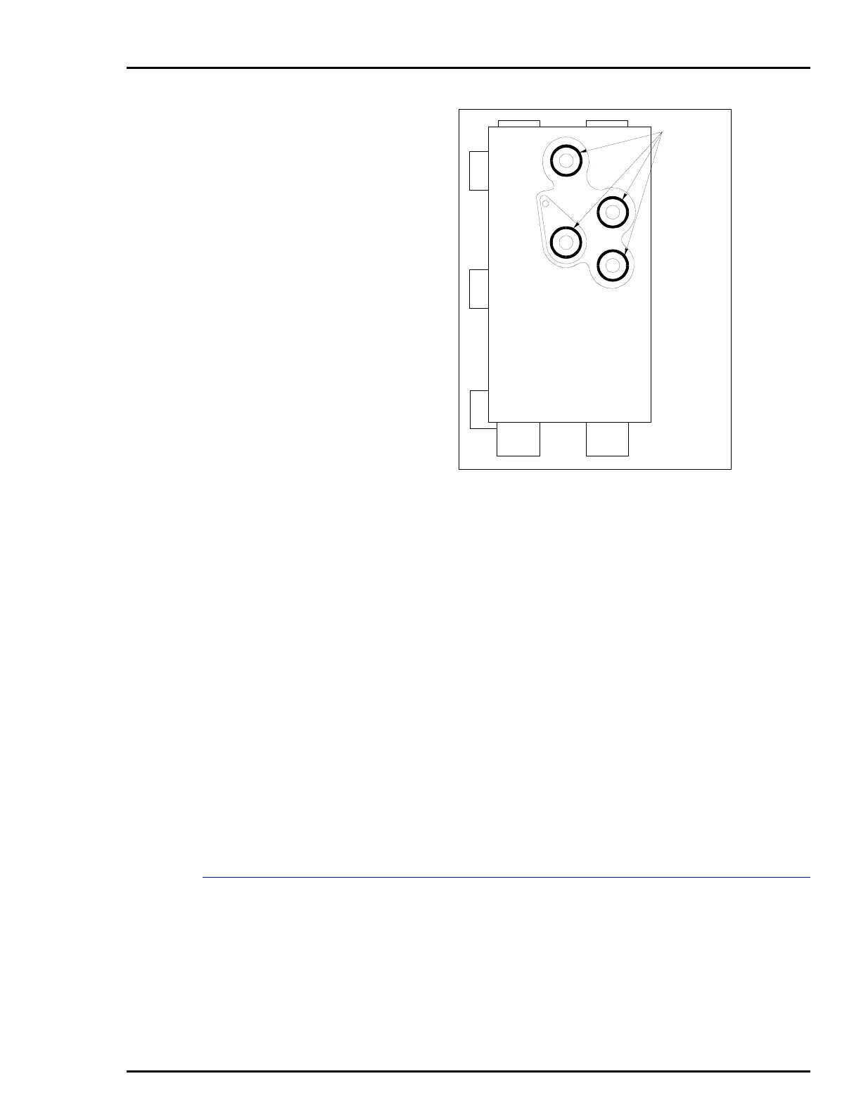
Figure 8-2. Manifold O-Rings
 Loading...


