INSTALLATION
MOUNTING TYPE AV POSITIONERS
3 - 7
square function (Table 3-1). Cam B is in place when the positioner
is shipped from the factory. The cams may be shaped to conform
to special applications. Refer to Appendix C for information about
cam shaping.
NOTE: If the application is reverse acting, the reverse acting
cam (red radial lines) must be installed and the connections to
ports 01 and 02 must be reversed.
The cam, camshaft and drive arm rotate as an assembly. Cam
motion is 90 degrees (Type AV__2____) or 45 degrees (Type
AV__1____) depending on the positioner type specified by
nomenclature (Figure 3-7).
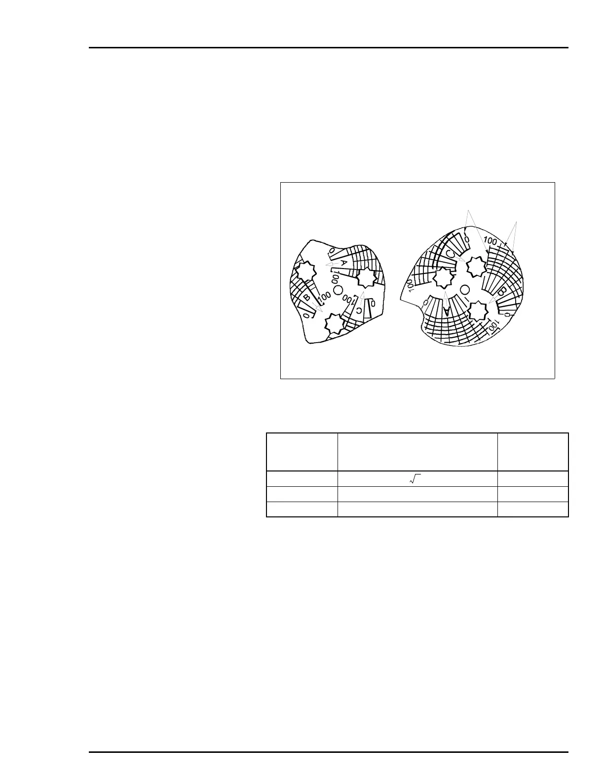
Each cam shape (A, B or C) has its own eight-point center hole for
mounting on the camshaft (Fig. 3-7). Place the cam in one of the
eight 45-degree positions so that the midpoint of the cam corre-
sponds to the mid stroke of the actuator. The drive arm should be
perpendicular to the motion of the actuator with the actuator at mid
stroke.
3. Adjust the connecting linkage so that the zero radial line on
the cam intersects the center of the cam roller when the actuator
is at its zero position (Fig. 3-8).
Figure 3-7. Cam
Table 3-1. Cam Characteristics
Positioning
Cam
Any Stroke
Piston or Valve Position (P)
vs
Control Signal (I)
Figure
Number
A
Square root
C-1
B
Linear
C-2
C
Square
C-3
ARCS
RADIAL
LINES
45° CAM
AV??1????
90° CAM
AV??2????
 Loading...


