QUICK START
TYPE AV2 POSITIONER WIRING
B - 9
3. If equipped with optional potentiometric position transmitter
(AV2___1__), connect a power supply (maximum 35 VDC or 30 VAC)
across TB1-1 and TB1-3. Use the signal across TB1-1 and TB1-2 or
TB1-2 and TB1-3 for position transmitter feedback. Refer to
Appendix A for detailed information about position transmitters.
NOTE: Route the wiring inside the positioner so it does not become
entangled with moving parts. A cable clamp (Figure B-12) is pro-
vided inside the positioner so entanglement can be avoided.
Figure B-11. Wiring Connections
NOMENCLATURE
AV23?????
AV33?????
AV44?????
AV????1??
AV????2??
123
TB1 CONNECTIONS
T00807A
45
+–
+–
+–
+24
+–
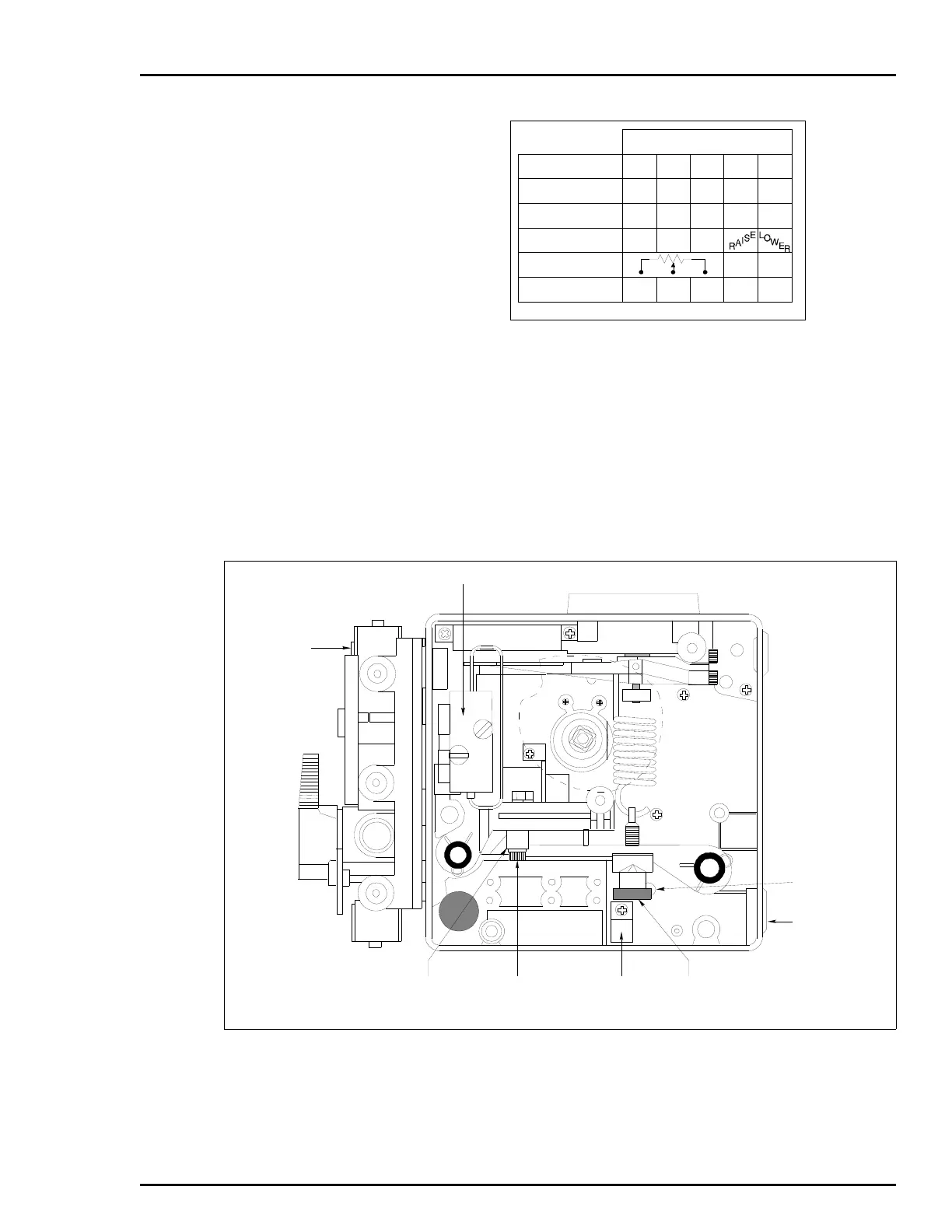
Figure B-12. Calibration Adjustments
OPTIONAL
MANIFOLD
PILOT VALVE
CONDUIT
HOLE
ZERO
ADJUSTMENT
NUT
T00774A
CABLE
CLAMP
SPAN
ADJUSTMENT
SCREW
SPAN
ADJUSTMENT
ASSEMBLY
ZERO
ADJUSTMENT
SET SCREW
 Loading...


