CALIBRATION
GAIN AND SPEED ADJUSTMENTS
4 - 7
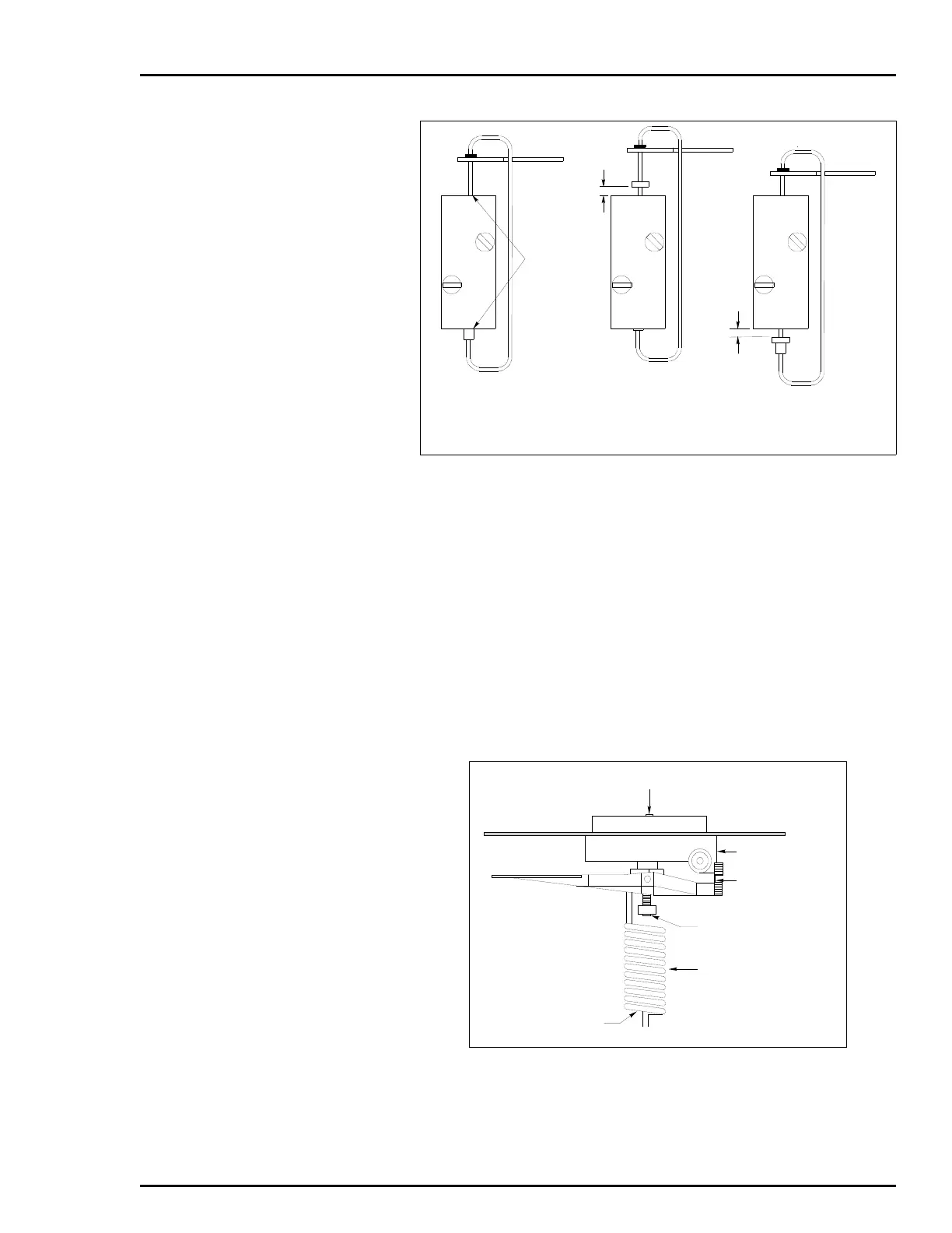
2. Use a -inch Allen wrench (the wrench must be at least
5-inches long) to turn the lower adjustment screw clockwise the
same amount as the top adjustment screw to insure speed of
operation is the same in both directions (if desired). Be careful
when accessing the lower adjustment screw. Insert the Allen
wrench up through the bottom of the range spring (Fig. 4-6). This
adjustment controls the amount of air going to port 02.
NOTE: To adjust the pilot valve stroke to the factory setting, refer
to PILOT VALVE STROKE ADJUSTMENT in Section 8.
3. Test for satisfactory stroke time and adjust as required.
Figure 4-5. Pilot Valve Adjustment
Figure 4-6. Speed Adjustment Screws
STEM IS
FLUSH
WITH BODY
0.030
0.030
STEM POSITION AT
BALANCE CONDITION
STEM POSITION TOP
ADJUSTMENT SCREW
STEM POSITION LOWER
ADJUSTMENT SCREW
T00777A
LOWER ADJUSTMENT
SCREW
HINGE SPRING
SIGNAL
DIAPHRAGM
TOP ADJUSTMENT SCREW
RANGE SPRING
ALLEN WRENCH
ACCESS
T00778A
 Loading...


