INSTALLATION
TUBING CONNECTIONS
3 - 9
Positioners equipped with manifolds have three secondary filters
as part of the unit. If the filters become clogged, they can be
cleaned (by removing and reverse flushing with air or liquid) or
replaced (refer to Table 1-7 for kit number). Refer to Section 7 for
manifold filter replacement procedures.
Air Supply Quality (Recommended)
For long-term, trouble free operation, it is recommended that the
supply air be of instrument quality and conform to the ANSI/
ISA-7.0.01-1996 standard that includes the following:
• The pressure dew point as measured at the dryer outlet shall
be at least 10
o
C (18
o
F) below the minimum temperature to
which any part of the instrument air system is exposed. The
pressure dew point shall not exceed 4
o
C (39
o
F) at line pres-
sure.
• The oil content should be as close to zero as possible and,
under no circumstances, shall it exceed one (1) ppm w/w or
v/v.
• Instrument air should be free of corrosive contaminants and
hazardous gases, which could be drawn into the instrument air
supply.
In addition, the particle size in the supply line should not be
greater that 3.0 microns.
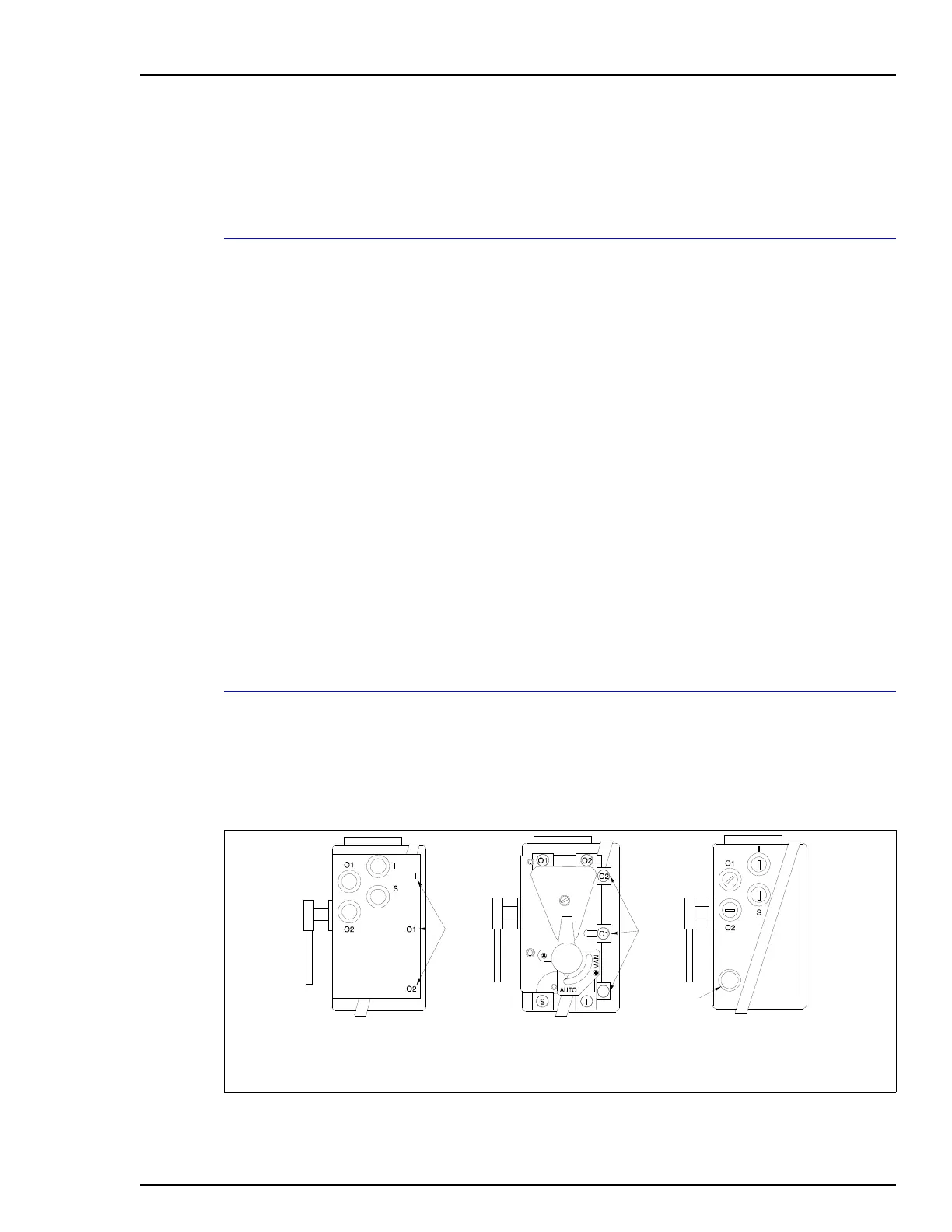
Tubing Connections
1. Connect the required air supply to connection S (Fig. 3-9).
NOTE: Use liquid or paste pipe sealant to seal the connection.
Maximum torque for ¼-NPT fittings is 13.6 Nm (10 ft-lbs).
Figure 3-9. Port Locations
T00806A
VIEW WITH GAGE
BLOCK (AV???3???)
VIEW WITH MANIFOLD
(AV???1??? OR
AV???2???)
VIEW WITHOUT
MANIFOLD
(AV???0???)
GAGE
PORTS
GAGE
PORTS
CONDUIT
CONNECTION
 Loading...


