QUICK START
TYPE AV2 POSITIONER WIRING
B - 8
TYPE AV2 POSITIONER WIRING
This section covers the wiring connections for Type AV2
positioner:
1. Connect the four to 20-mA position demand signal wires to termi-
nals TB1-4 (+) and TB1-5 (-) of the terminal block (Fig. B-11). If you
have a Type AV2___0__ positioner, go to Step 4.
NOTE: If using a twisted shielded pair for signal wiring, ground one
end of the shielded pair at the source. Trim the other end of the pair,
located inside the enclosure, so that bare wires are not exposed.
2. If equipped with an optional 4 to 20-mA position transmitter
(AV2___2__), connect a 24-VDC power supply in series with the
required output load (Table 1-5) to terminals TB1-1 (+) and TB1-2 (-).
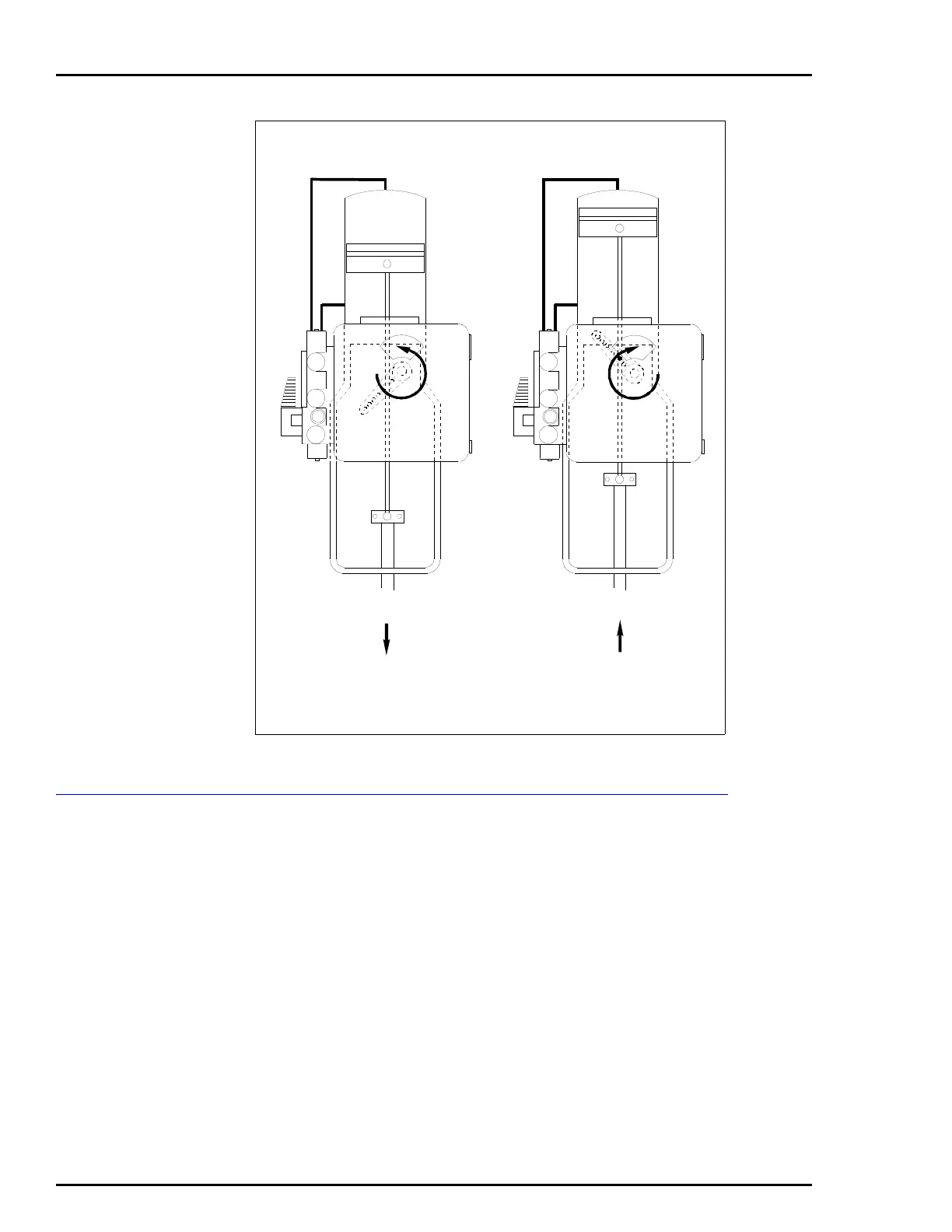
Figure B-10. Double Acting Tubing Example
NOTE: IN ANY INSTALLATION, DIRECTION OF PISTON TRAVEL CAN BE REVERSED BY
USING THE REVERSE ACTING CAM (LOCATED IN POSITIONER COVER) AND REVERSING
THE O1 AND O2 CONNECTIONS. GAGE DESIGNATIONS:
G1 = SIGNAL GAGE
G2 = OUTPUT GAGE (O1 PORT)
G3 = OUTPUT GAGE (O2 PORT)
T00773A
DIRECT ACTING
(BLACK) CAM
O1
O2
G3 G3
G2 G2
G1 G1
O1
O2
REVERSE ACTING
(RED) CAM
MOTION WITH
INCREASING SIGNAL
MOTION WITH
INCREASING SIGNAL
 Loading...


