CAM CHARACTERIZATION
CAM SELECTION
C - 3
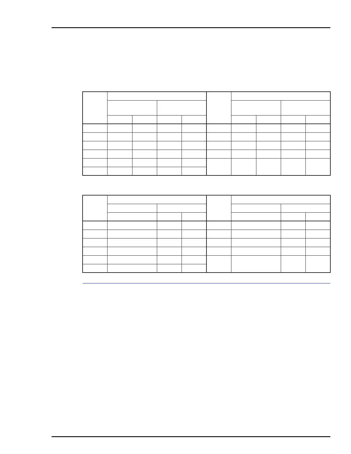
Table C-1 relates the percentage of control signal to the corre-
sponding pressure values of the input signal. Table C-2 relates the
percentage of control signal to input (current) and output (pounds
per square inch gage) values of the I/P converter.
CAM SELECTION
In a system involving only a single actuator or cylinder, the B cam
is probably satisfactory and should be tried first. However, one of
the other cams may provide a more stable control over a wide
range of operation within a given proportional band gain adjust-
ment on the controller. Where the actuator or cylinder is part of a
complex control system, the three standard cams A, B and C pro-
vide a choice of control characteristics. The cam, in conjunction
with a span adjustment, are likely to meet the control characteris-
tic required for the system.
Steps is selecting a standard cam for a particular application are:
1. With the B (linear) cam in place, determine and plot the actual
controlled medium versus piston (or valve) position characteristic
by manually adjusting valve position and measuring the controlled
medium (Fig. C-4).
Table C-1. Control Signal Pressure Conversions (AV1)
% of
Control
Signal
Control System Spans
% of
Control
Signal
Control System Spans
20.7 to 103.4 kPa
(3.0 to 15.0 psig)
20.7 to 186.2 kPa
(3.0 to 27.0 psig)
20.7 to 103.4 kPa
(3.0 to 15.0 psig)
20.7 to 186.2 kPa
(3.0 to 27.0 psig)
kPa psig kPa psig kPa psig kPa psig
0 20.7 3.0 20.7 3.0 60 70.3 10.2 120.0 17.4
10 29.0 4.2 37.3 5.4 70 78.6 11.4 136.6 19.8
20 37.2 5.4 53.8 7.8 80 86.9 12.6 153.1 22.2
30 45.5 6.6 70.4 10.2 90 95.2 13.8 169.7 24.6
40 53.8 7.8 86.9 12.6 100 103.4 15.0 186.2 27.0
50 62.1 9.0 103.5 15.0
Table C-2. Input to Output I/P Converter Relationships (AV2)
% of
Control
Signal
I/P Converter
% of
Control
Signal
I/P Converter
Input Output Input Output
mA kPa psig mA kPa psig
0 4.0 20.7 3.0 60 13.6 70.3 10.2
10 5.6 29.0 4.2 70 15.2 78.6 11.4
20 7.2 37.2 5.4 80 16.8 86.9 12.6
30 8.8 45.5 6.6 90 18.4 95.2 13.8
40 10.4 53.8 7.8 100 20.0 103.4 15.0
50 12.0 62.1 9.0
 Loading...


