INTRODUCTION
C - 1
APPENDIX C - CAM CHARACTERIZATION
INTRODUCTION
This section provides cam shaping information. Cam shaping is
the process of changing the shape of the cam by cutting or form-
ing so the control signal produces the desired control characteris-
tic. The standard cam normally does not require shaping.
CAM CHARACTERIZATION
Selecting or shaping these cams allows you to obtain a piston (or
valve) position versus control signal characteristic that will pro-
duce a desired controlled medium versus control signal character-
istic. An example is a desired flow rate of air, water or steam
through a valve for each control signal pressure applied to the
positioner.
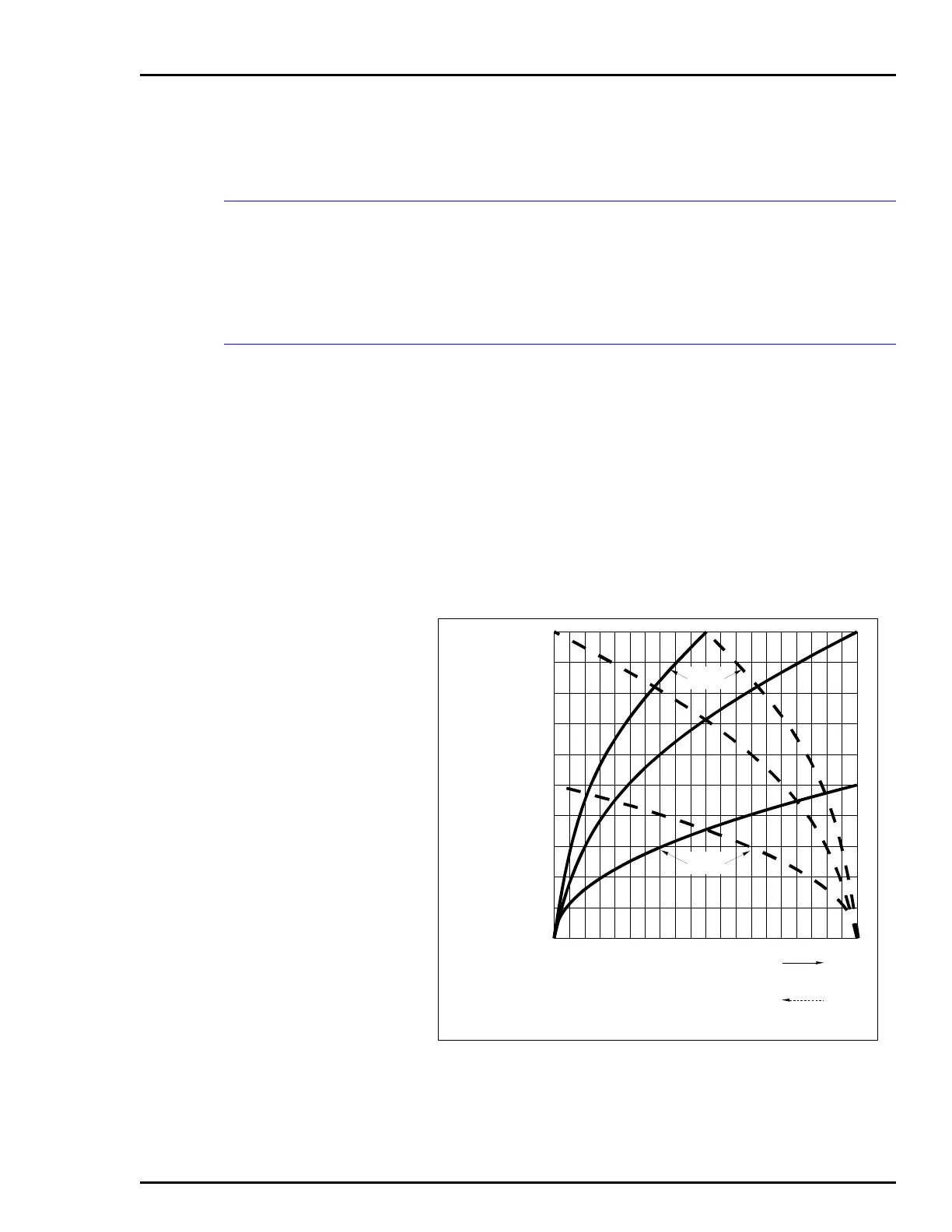
The control characteristics for which the cams are shaped are
listed in Table 3-1 and are shown in Figures C-1, C-2 and C-3. The
figures show a family of curves for each cam whose boundaries
are established by a span adjustment.
Figure C-1. Cam A, Square Root Relationship
100
40
10
20
30
90
50
60
70
80
0
SCALE = % OF
SIGNAL RANGE
SCALE = % TRAVEL
T00791A
0
100
20
80
30
70
40
60
50
50
10
90
60
40
70
30
80
20
90
10
100
0
SOLID LINE INDICATES FORWARD TRAVEL
DASHED LINE INDICATES REVERSE TRAVEL
LIMITED
SIGNAL
LIMITED
TRAVEL
 Loading...


