REPAIR AND REPLACEMENT
PILOT VALVE STROKE ADJUSTMENT
8 - 8
b. If manual override is not available, disconnect (and
secure) the linkage. Plug ports 01 and 02 if necessary.
2. Apply the supply pressure.
3. Apply the maximum input signal to the positioner:
• AV11: 103.4 kPa (15.0 psig).
• AV12:186.2 kPa (27.0 psig).
• AV23: 20 mA.
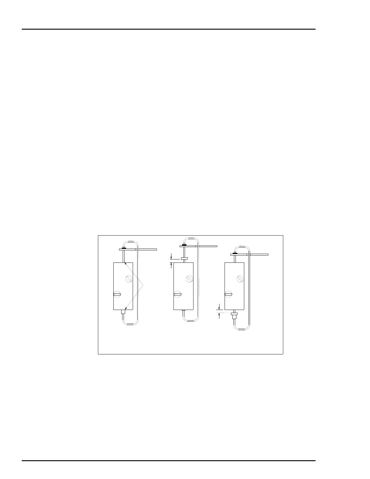
4. Use the long -inch Allen wrench, adjust the top adjustment
screw (Fig. 8-4) appropriately until the measurement matches the
value shown in Figure 8-3. Figure 8-3 also shows the way the mea-
surement is taken.
5. Apply the minimum input span to the positioner:
• AV11: 20.7 kPa (3.0 psig).
• AV12: 20.7 kPa (3.0 psig).
• AV23: 4 mA.
6. Use the long -inch Allen wrench to adjust the lower stroke
adjustment screw (Fig. 8-4). Adjust the screw until the measurement
matches the value shown in Figure 8-3.
Figure 8-3. Pilot Valve Measurement for Maximum Speed
STEM IS
FLUSH
WITH BODY
0.030
0.030
STEM POSITION AT
BALANCE CONDITION
STEM POSITION TOP
ADJUSTMENT SCREW
STEM POSITION LOWER
ADJUSTMENT SCREW
T00777A
 Loading...


