POSITION TRANSMITTERS
CALIBRATION
A - 4
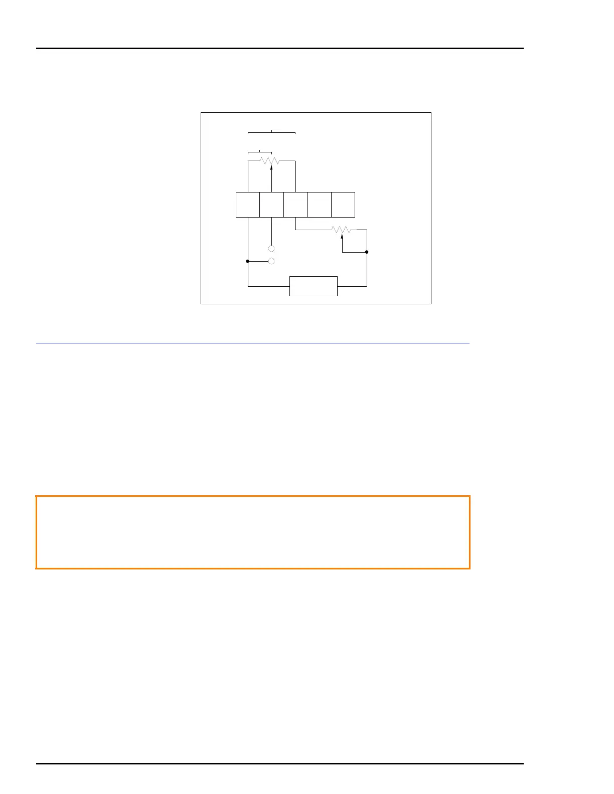
tolerance of the potentiometer. Figure A-2 is a schematic diagram
of this application example.
CALIBRATING THE POTENTIOMETRIC EXAMPLE
The calibration information is based on the application put forth in
POTENTIOMETRIC APPLICATION EXAMPLE.
1. Move the actuator to the 0% output position.
2. Remove the field wiring from TB1-1, TB1-2 and TB1-3. Using
an ohmmeter, measure the resistance between TB1-1 and TB1-2.
If the reading is 200, ±20 Ω, remove the ohmmeter and proceed to
Step 3. Otherwise continue with Step 2.
a. Remove the cam by removing the screw, flag, nut and
washer (Fig. A-3 and Table A-1).
b. Loosen the set screw on the hub of the small gear using a
-in. Allen wrench (Fig. A-3 and Table A-1).
c. Use a screwdriver to adjust the shaft on the potentiometer
until the ohmmeter reads 200, ±20 Ω. While adjusting the
resistance, hold the gears and cam shaft stationary so rotation
does not occur. Only the potentiometer shaft should move
while adjusting the resistance.
Figure A-2. Schematic Diagram
TB1
2000 ±20%
Ω
2380
NOMINAL
ADJUSTMENT
Ω
OUTPUT
24 VDC
T00787A
200-912.8
Ω
12345
+
+
–
–
WARNING
The pneumatic supply pressure must be turned off before
removing the positioning cam. The final control element will
go to one end of the stroke and can cause a process upset.
Some process upsets may cause damage to equipment and
endanger personnel.
 Loading...


