INSTALLATION
WIRING TYPE AV1 POSITIONER
3 - 13
WIRING TYPE AV1 POSITIONER
This section applies to the following positioners:
• Type AV1___1__.
• Type AV1___2__.
NOTES:
1. If this is a Type AV1___0__ positioner, no electrical wiring is
required.
2. If using a twisted shielded pair for signal wiring, ground one
end of the shielded pair at the source. Trim the other end of the
pair, located inside the enclosure, so that bare wires are not
exposed.
1. If equipped with an optional 4 to 20-mA position transmitter
(Type AV1___2__), connect a 24-VDC power supply in series with
the required output load (Table 1-5) to terminals TB1-1 (+) and
TB1-2 (-) (Figs. 3-2
and 3-15). Refer to Appendix A for detailed
information about position transmitters.
2. If equipped with an optional potentiometric position transmitter
(Type AV1___1__), connect a power supply (maximum 35 VDC or
30 VAC) across TB1-1 and TB1-3. Use the signal across TB1-1
and TB1-2 or TB1-2 and TB1-3 for position transmitter feedback.
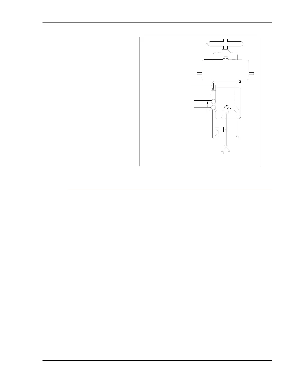
Figure 3-13. Reverse Acting, Bottom Loaded,
Single Acting Tubing Example
G2
G1
HANDJACK
O1
OUTPUT GAGE (O1 PORT)
SIGNAL GAGE
T00891A
MOTION WITH
INCREASING SIGNAL
NOTES:
1. RED CAM ROTATES CLOCKWISE WHEN
VIEWED FROM THE FRONT.
2. O2 PORT PLUGGED.
3. STEM MOVES DOWN WITH SIGNAL OR
SUPPLY AIR FAILURE.
 Loading...


