CALIBRATION
GAIN AND SPEED ADJUSTMENTS
4 - 5
GAIN AND SPEED ADJUSTMENTS
Gain and speed adjustment information applies to both the Type
AV1 and Type AV2 positioners. This is the gain of the overall posi-
tioner. The factory-installed 0.25-millimeter (0.100-inch) gain
hinge spring suits most applications. This adjustment is not a
mandatory part of calibration.
Gain Adjustment
Gain adjustment on the Type AV positioners is accomplished by
changing the gain hinge spring (Item 7, Figs. 9-3 or 9-4) connect-
ing the beam assembly to the positioner housing. Provided with
each positioner are two different gain hinge springs. If actuator
oscillation occurs, the overall positioner gain may be too high.
Positioner gain is related to the thickness of the gain hinge spring.
Gain decreases as the thickness of the gain hinge spring
increases. Refer to Table 4-1 for hinge information.
For information on changing the gain hinge spring, refer to Gain
Hinge Spring in Section 8.
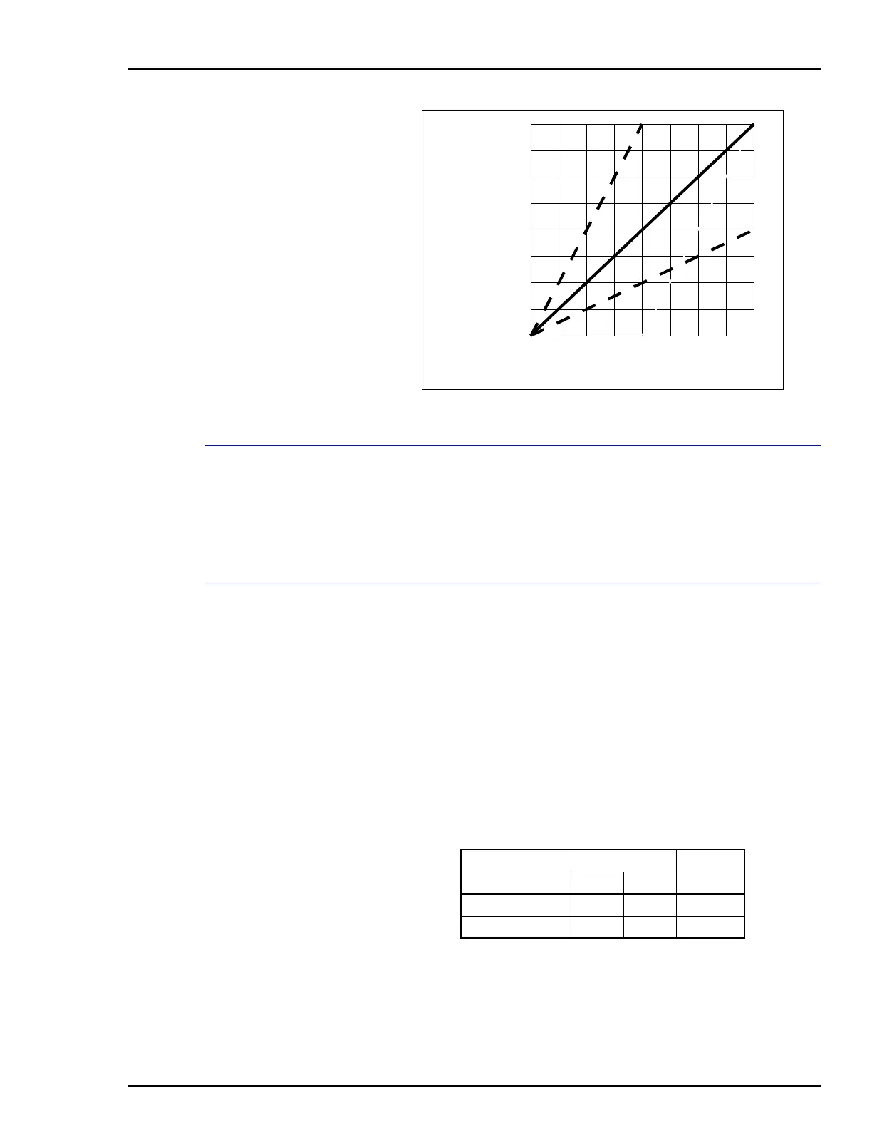
Figure 4-4. Span Adjustment Graph
OUTPUT
POSITION
(0 TO 100%
TRAVEL)
INPUT SIGNAL
(0 TO 100%)
T00776A
100
50
0
0 50 100
Table 4-1. Gain Hinge Springs
1
Part Number
Thickness
Gain
mm in.
5400264_1
2
0.25 0.010 High
5400264_2 0.76 0.030 Medium
NOTES:
1. For small actuators, it may be necessary to combine both
gain hinge springs.
2. The high gain hinge spring comes installed from the fac-
tory.
 Loading...


