Installation
28
1SVC 440 795 M0100
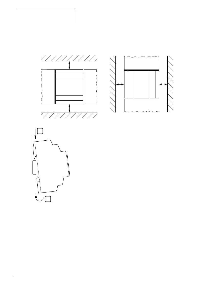
For ease of wiring, leave a gap of at least 30 mm between
the terminals and the wall or adjacent devices.
Figure 4: Clearances from the logic relay
Mounting on top-hat rail
X Place the logic relay diagonally on the upper lip of the
top-hat rail. Slightly push the device down and against the
top-hat rail until it also snaps onto the bottom lip of the
rail.
The logic relay will clip into place and will be secured by the
built-in spring mechanism.
X Check that the device is seated firmly.
The device is mounted vertically on a top-hat rail in the same
way.
30
30
30
30
1
2
 Loading...


