Wiring with the logic relay
84
1SVC 440 795 M0100
Checking the circuit diagram
The logic relay contains a built-in measuring device enabling
you to monitor the switching states of contacts and relay
coils during operation.
X Complete the small parallel connection and switch the
logic relay to RUN mode via the main menu.
X Return to the circuit diagram display.
You are now unable to edit the circuit diagram.
The circuit diagram display performs two functions
depending on the mode:
• STOP: Creation of the circuit diagram
• RUN: Power flow display
X Switch on I3.
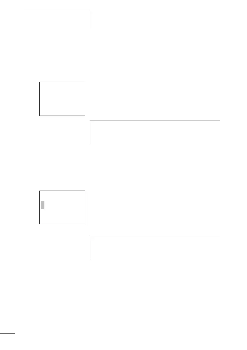
In the power flow display, energized connections are thicker
than non-energized connections.
You can follow energized connections across all rungs by
scrolling the display up and down.
I2---u---ÄQ4
I3---k
h
If you switch to the circuit diagram display and are unable
to modify a circuit diagram, first check whether the logic
relay is in STOP mode.
I2---U---ÄQ4
I3---k
h
The power flow display will not show signal fluctuations in
the millisecond range.This is due to the inherent delay
factor of LCD displays.
 Loading...


