Installation
46
1SVC 440 795 M0100
20 mA sensor
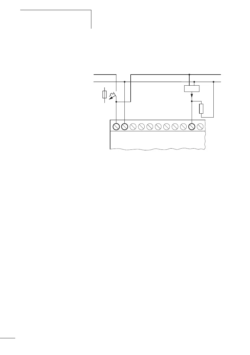
4 to 20 mA (0 to 20 mA) sensors can be connected easily
without any problem using an external 500 V resistor.
Figure 24: Connection 0 (4) to 20 mA sensor output, analog input
Analog sensor
The following values apply:
•4 mA = 1.9 V
•4 mA = 1.9 V
• 20 mA = 9.5 V
(Based on U = R I = 478 10 mA 苲 4.8 V).
Connecting high-speed counters and frequency
generators
High-speed counter signals and frequencies on the CL-DC1
and CL-DC2 can be counted accurately on inputs I1 to I4
independently of the cycle time. These inputs are
permanently assigned to counters.
The coils and contacts have the following meanings:
• I1 = C13 high-speed up/down counter
• I2 = C14 high-speed up/down counter
• I3 = C15 frequency counter
• I3 = C15 frequency counter
L01
F1
L01
햲
500
4...20 mA
I7+...V 0 V0 V
DC1 : +24 V
DC2 : +12 V
 Loading...


