Wiring with the display system
190
1SVC 440 795 M1100
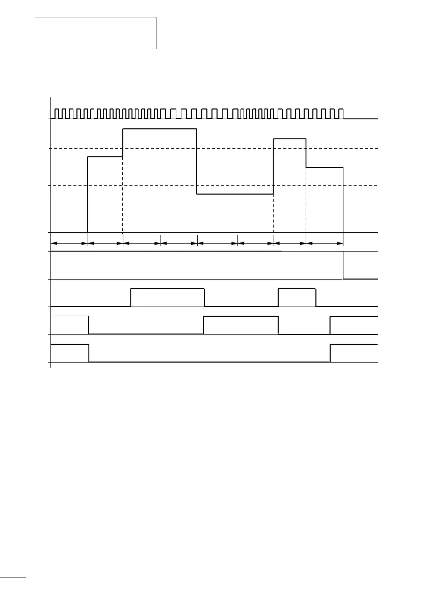
Function of the frequency counter function block
Figure: 102: Signal diagram of frequency counter
1: Counter input I1 to I4
2: Upper setpoint value
>SH
3: Lower setpoint value >SL
4: Enable CF..EN
5: Contact (N/O contact) CF..OF upper setpoint value exceeded
6: Contact (N/O contact) CF..FB lower setpoint value undershot
7: Actual value equal to zero CF..ZE
t
g
: Gate time for the frequency measurement
• The first measurements are made after the CF..EN enable signal
has been activated. The value is output after the gate time has
timed out.
• The contacts are set in accordance with the measured frequency.
• If the CF..EN enable signal is removed, the output value is set to
zero.
1
2
3
4
t
g
t
g
t
g
t
g
t
g
t
g
t
g
t
g
5
6
7
 Loading...


