Installation
56
1SVC 440 795 M1100
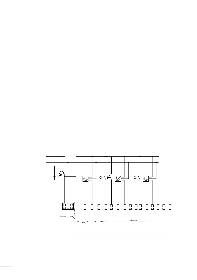
Connecting DC display I/O modules
Use input terminals I1 to I12 to connect pushbutton
actuators, switches or 3 or 4-wire proximity switches. Do not
use any 2-wire proximity switches due to the high residual
current.
Input signal voltage range
• I1 to I6, I9, I10
– Off signal: 0 to 5 V
– On signal: 15 to 28.8 V
• I7, I8, I11, I12
– Off signal: < 8 V
–On signal: >8V
Input current
• I1 to I6, I9, I10, R1 to R12: 3.3 mA at 24 V
• I7, I8, I11, I12: 2.2 mA at 24 V
Figure: 39: DC display I/O module
L01–
> 1 A
L01+
I1 I3 I4 I7 I8 I9 I10
L02+
I2 I5 I6 I11
I12
+24V 0V 0V
h
The digital inputs must be fed with the same voltage as
the power supply of the display base module.
 Loading...


