Wiring with the display system
216
1SVC 440 795 M1100
The display system provides 32 seven-day time switches
HW01 to HW32 for a total of 128 switching times. Each time
switch has four channels which you can use to set four on and
off times. The channels are set via the parameter display.
The timer has a back-up battery, although the time switch
relays will no longer switch. When the device is in a
de-energized state, the timer contacts remain open. Refer to
chapter “Technical data”, page 389, for information on the
buffer time.
Wiring of a 7-day time switch
You integrate a 7-day time switch in the circuit diagram as a
contact.
Figure: 114: Display system circuit diagram with 7-day time
switch
Parameter display and parameter set for the 7-day time
switch HW:
Channels
4 channels are available per time switch, channels A, B, C
and D. These channels all act on the contact of the 7-day
time switch.
Day 1 and day 2
Either day 1 to day 2, e.g. Monday to Friday, or only day 1.
Monday = MO, Tuesday = TU, Wednesday = WE,
Thursday = TH, Friday = FR, Saturday = SA, Sunday = SU,
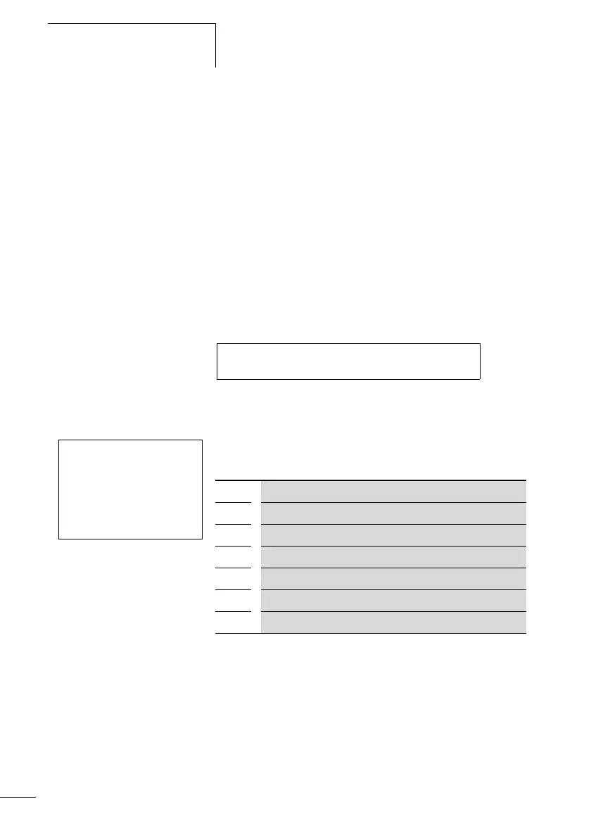
HW14Q1---------------------------Ä Q 01
HW14 A +
>DY1
>DY2
>ON
>OFF
HW14 7-day time switch function block number 14
A Time switch channel A
+ Appears in the parameter display
>DY1 Day 1
>DY2 Day 2
>ON on time
>OFF off time
 Loading...


