Installing the module
WARNING!
Obey the safety instructions. If you ignore the safety instructions, injury or death
can occur.
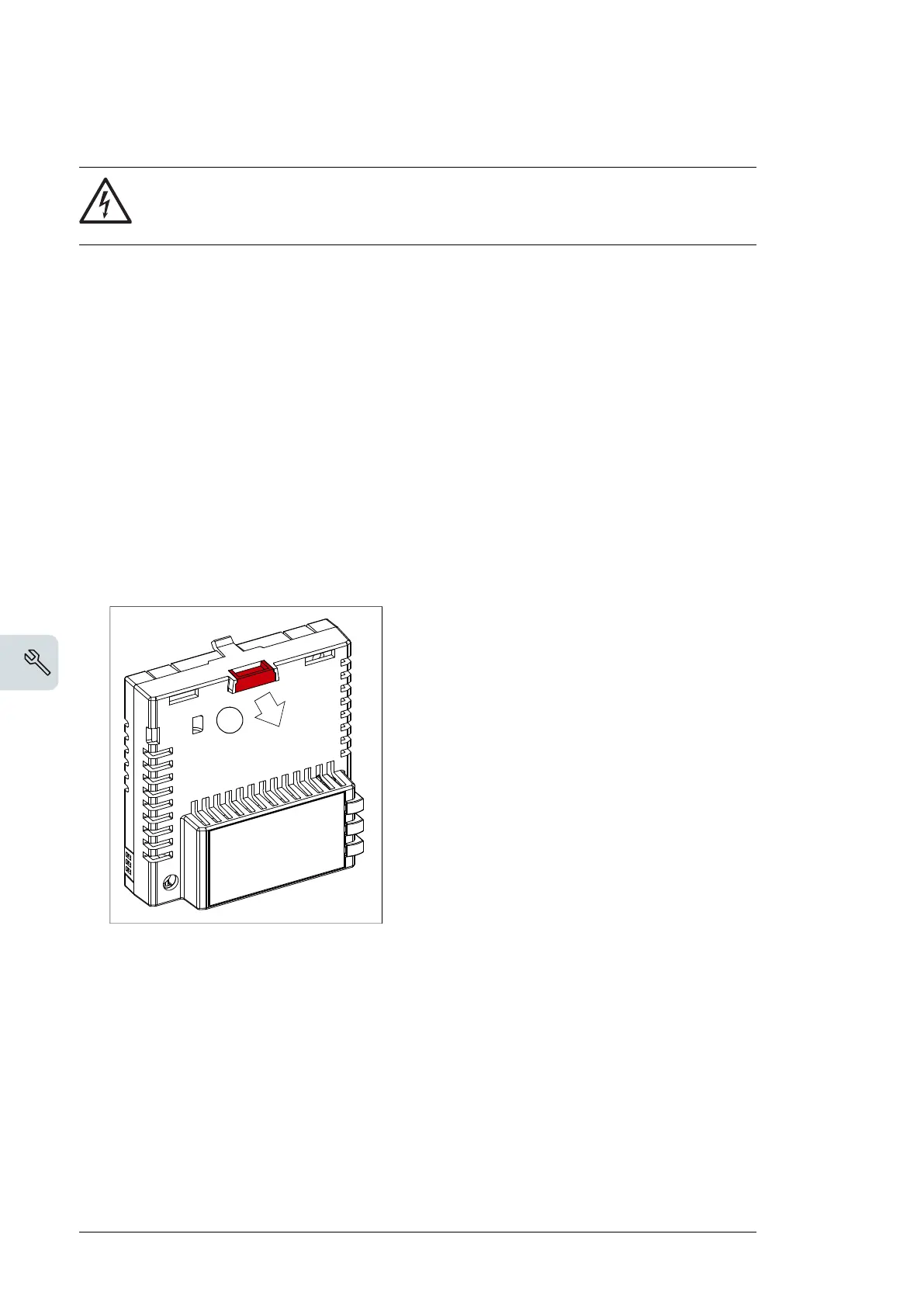
The module is installed to a free option slot on the drive control unit. Plastic pins, a lock and
one screw hold the module in place. The screw also makes an electrical connection between
the module and drive frame for cable shield termination.
Note:
FSPS-21 is an option for inverter units only. In drives with separate supply and inverter
units, FPNO-21 or FENA-21 module must be used for fieldbus communication in the supply
unit.
Note:
Do not install the FSPS-21 module on the FEA-03 F-series extension adapter.
When the module is installed, it makes the signal and power connection to the drive through
a 20-pin connector.
To install or remove the module from the control unit:
1. Pull out the lock.
Options for ABB drives, converters and inverters
Quick installation and start-up guide
FENA-21 Ethernet adapter module
Safety instructions
WARNING! Obey the safety instructions. If you ignore them, injury or death, or damage to the
equipment can occur. See the user’s manual.
Mechanical installation
Electrical installation
Layout of the module
1
3
4
1. Pull out the lock.
2. Install the module carefully to an option
module slot of the drive. See the drive
hardware manual.
3. Push in the lock.
4. Tighten the screw to torque 0.8 N·m using
a Torx TX10 screwdriver.
WARNING! Do not use excessive force,
or leave the screw too loose. Over-
tightening damages the screw or
module. A loose screw decreases the EMC
performance, and can even cause an operation
failure.
No. Description
1Lock
2 Mounting and grounding screw
3 RJ-45 connector [X1] to Ethernet
4 RJ-45 connector [X2] for chaining another module
5 Diagnostic LEDs
5
3
2
4
1
2. Install the module carefully to an option module slot of the drive. See the drive hardware
manual.
36 Mechanical installation

 Loading...


