4.8 Gearboxes
4.8.1 Replacement of gearbox, axis 1-3
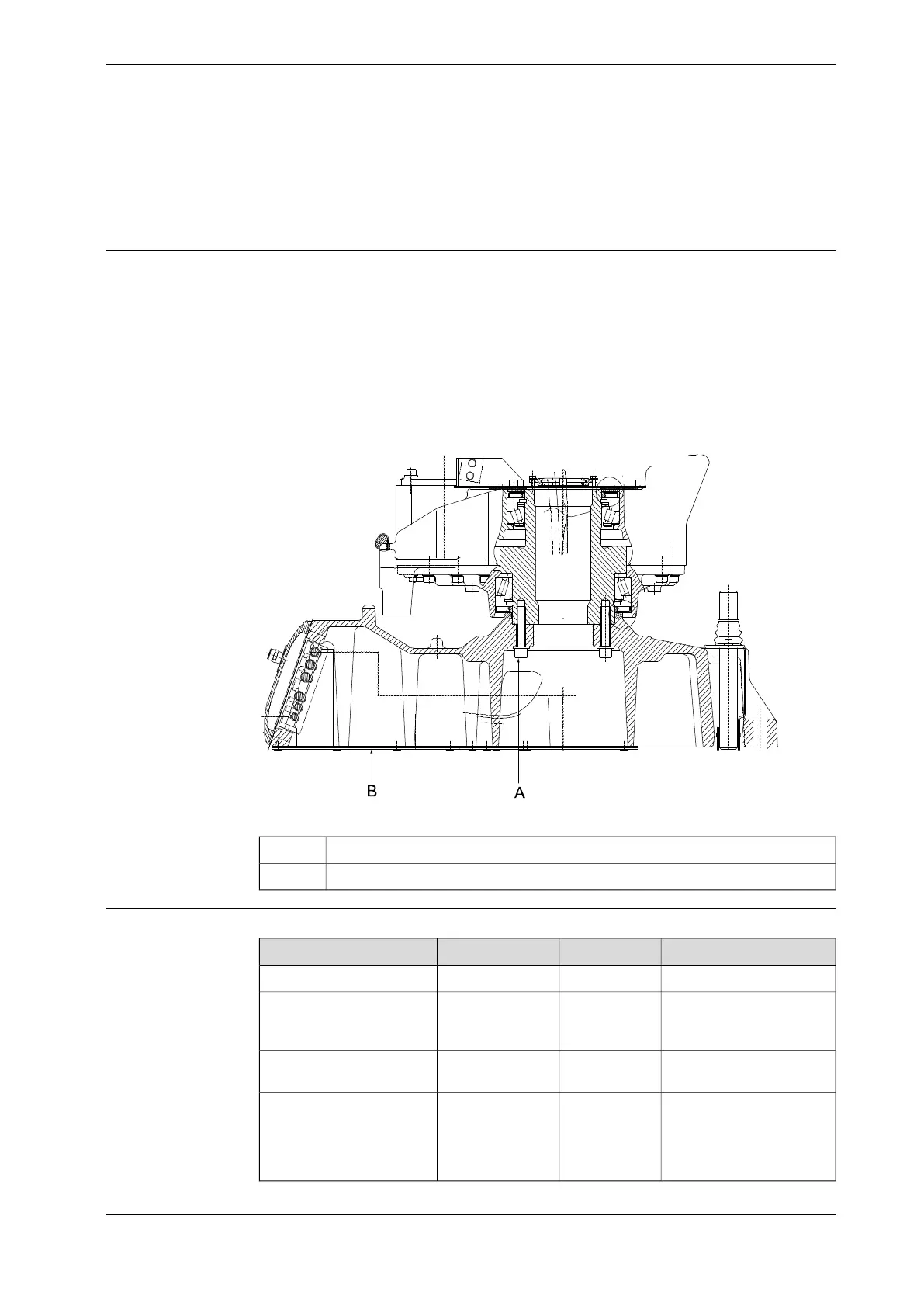
Location of gearbox, axis 1-3
The axis 1 gearbox is located between the frame and base as shown in the figure
below.
Axis 1 gearbox is of the conventional type, manufactured with high precision.
Together with the gearboxes for axes 2 and 3, it forms a complete unit.
A more detailed view of the component and its position may be found in chapter
Spare part lists on page 233.
Note! The gearbox is not normally serviced or adjusted.
xx0300000007
Attachment screws, gearbox unitA
Bottom plateB
Required equipment
NoteArt. no.Spare part no.Equipment
3HAC025711-001Gearbox, axes 1-3
The content is defined in
the section Standard tools
on page 229.
-Standard toolkit
Complete kit that also in-
cludes operating manual.
3HAC15716-1Calibration Pendulum
toolkit
These procedures include
references to the tools re-
quired.
Other tools and procedures
may be required. See refer-
ences to these procedures
in the step-by-step instruc-
tions below.
Continues on next page
Product manual - IRB 2400 197
3HAC022031-001 Revision: P
© Copyright 2004-2018 ABB. All rights reserved.
4 Repair
4.8.1 Replacement of gearbox, axis 1-3
 Loading...


