4.8.2 Replacement of drive shaft unit, IRB 2400L
Location, drive shaft unit
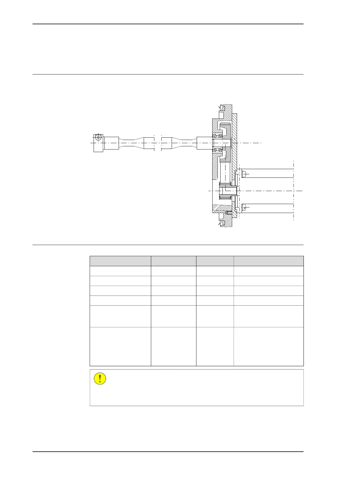
The drive shaft unit is defined as the gears and drive belts to axes 5 and 6. This is
shown in the figure below.
xx0300000012
Required equipment
NoteArt. no.Spare part no.Equipment, etc.
3HAC11804-1Drive shaft unit, axes 5-6
2 pcs3HAA2393-1Gear belt
3HAA7601-50Adjustment tool
-Lifting device, robot
The content is defined in the
section Standard tools on
page 229.
Standard toolkit
These procedures include
references to the tools re-
quired.
Other tools and proced-
ures may be required.
See references to these
procedures in the step-
by-step instructions be-
low.
CAUTION
Always cut the paint with a knife and grind the paint edge when disassembling
parts. See Cut the paint or surface on the robot before replacing parts on page 117.
Continues on next page
200 Product manual - IRB 2400
3HAC022031-001 Revision: P
© Copyright 2004-2018 ABB. All rights reserved.
4 Repair
4.8.2 Replacement of drive shaft unit, IRB 2400L
 Loading...


