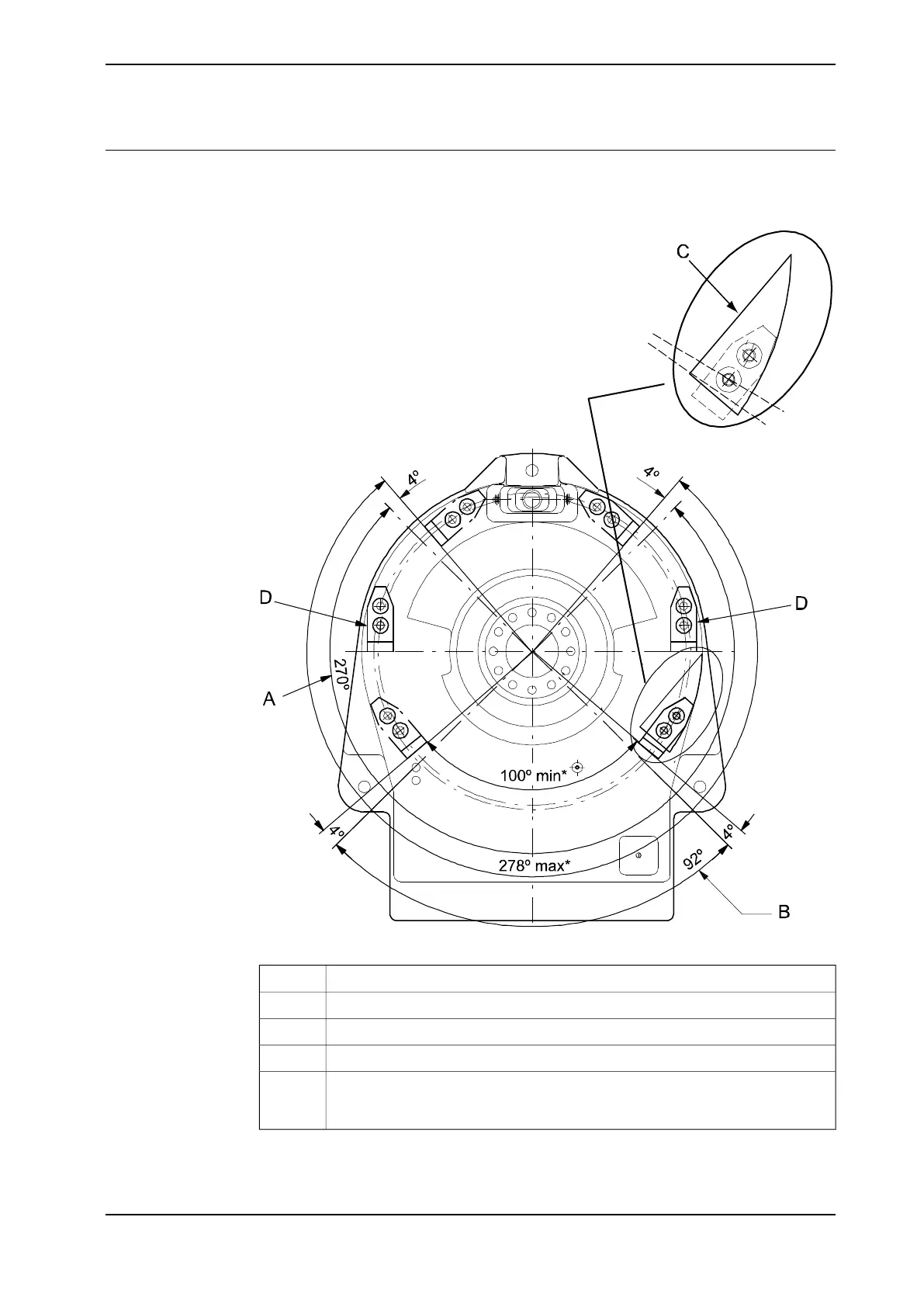
Location of where to drill holes for extra stops
The figure below shows the drill pattern used when drilling for mechanical stops
on axis 1.
xx0200000206
Maximum working range, axis 1A
Minimum working range, axis 1B
Drilling pattern enclosed with the mechanical stop.C
This mounting direction onlyD
The minimum and maximum measurement between the mechanical stops. The
difference between the measurement and the minimum and maximum working
range is 2 x 4º, which corresponds to the width of the stop pin (at the frame).
*
Continues on next page
Product manual - IRB 2400 75
3HAC022031-001 Revision: P
© Copyright 2004-2018 ABB. All rights reserved.
2 Installation and commissioning
2.4.2 Mechanically restricting the working range of axis 1
Continued

 Loading...


