NoteArt. no.Equipment, etc.
24 VDC, 1.5 A-Power supply
For releasing the brakes.
Used to rotate the motor pinion
when mating it to the gear, when
brakes are released with 24 VDC
power supply.
Rotation tool
Content is defined in section
Standard tools on page 381.
Standard toolkit
These procedures include refer-
ences to the tools required.
Other tools and procedures
may be required. See refer-
ences to these procedures
in the step-by-step instruc-
tions below.
See chapter Circuit diagram on
page 389.
3HAC025744-001Circuit diagram
Deciding calibration routine
Decide which calibration routine to be used, based on the information in the table.
Depending on which routine is chosen, action might be required prior to beginning
the repair work of the robot, see the table.
NoteAction
Decide which calibration routine to use for
calibrating the robot.
• Reference calibration. External cable
packages (DressPack) and tools can
stay fitted on the robot.
• Fine calibration. All external cable
packages (DressPack) and tools
must be removed from the robot.
1
Follow the instructions given in the refer-
ence calibration routine on the FlexPendant
to create reference values.
If the robot is to be calibrated with refer-
ence calibration:
Find previous reference values for the axis
or create new reference values. These val-
ues are to be used after the repair proced-
ure is completed, for calibration of the ro-
bot.
Creating new values requires possibility to
move the robot.
Read more about reference calibration for
Axis Calibration in Reference calibration
routine on page 353.If no previous reference values exist, and
no new reference values can be created,
then reference calibration is not possible.
Read more about reference calibration for
Pendulum Calibration in Operating manu-
al - Calibration Pendulum.
If the robot is to be calibrated with fine
calibration:
Remove all external cable packages
(DressPack) and tools from the robot.
Removing motors axes 2 and 3
Use this procedure to remove motors axes 2 and 3.
NoteAction
Decide which calibration routine to use, and
take actions accordingly prior to beginning the
repair procedure.
1
Continues on next page
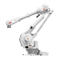
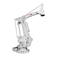
282 Product manual - IRB 6660
3HAC028197-001 Revision: S
© Copyright 2007-2018 ABB. All rights reserved.
4 Repair
4.6.2 Replacing motors, axes 2 and 3
Continued

 Loading...