EasyManuals Logo
Home>ABB>Controller>RMC-100

ABB RMC-100 Startup Guide

ABB RMC-100
40 pages
To Next Page IconTo Next Page
To Previous Page IconTo Previous Page
Page #14 background imageLoading...
Page #14 background image
14 | RMC-100 | 2105551MNAD
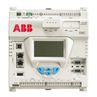
Table 4-4: Analog output pinouts
Output
PIN
Description
1
1
PWR - Loop power input
2
SNK - Current sink input
3
SRC - Current source output
4
GND - Ground
Figure 4-4: Analog output pinouts
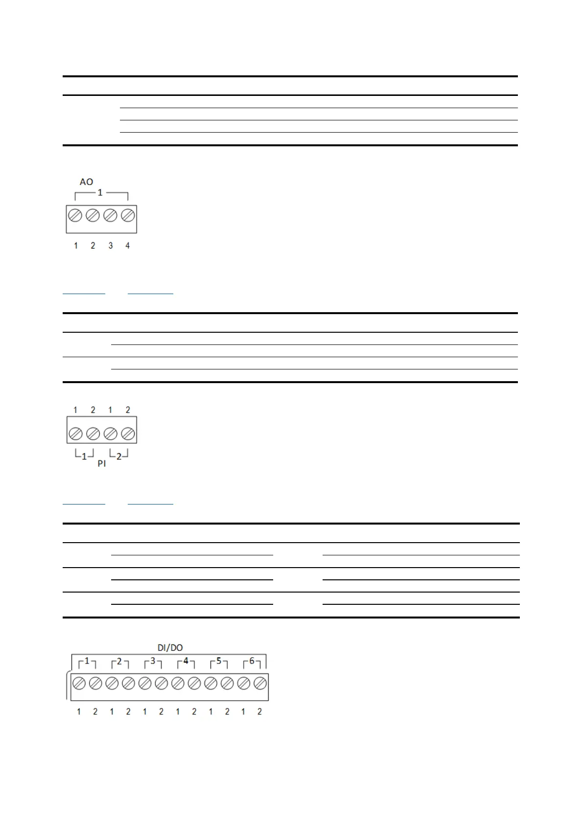
4.4.3 Pulse input pinouts
Table 4-5 and Figure 4-5 identify the PI pinouts.
Table 4-5: Pulse input pinouts
Input
PIN
Description
1
1
INP - Pulse input 1
2
GND - Ground
2
1
INP - Pulse input 2
2
GND - Ground
Figure 4-5: Pulse input pinouts
4.4.4 Digital input and output pinouts
Table 4-6 and Figure 4-6 identify the DI/DO pinouts.
Table 4-6: Digital I/O pinouts
DI/DO
PIN
Description
DI/DO
PIN
Description
1
1
SIGSignal DI/DO 1
1
1
SIGSignal DI/DO 4
2
GNDground
2
GNDground
2
1
SIGSignal DI/DO 2
2
1
SIGSignal DI/DO 5
2
GNDground
2
GNDground
3
1
SIGSignal DI/DO 3
3
1
SIGSignal DI/DO 6
2
GNDground
2
GNDground
Figure 4-6: Digital I/O pinouts

Table of Contents

Other manuals for ABB RMC-100

Questions and Answers:

Question and Answer IconNeed help?

Do you have a question about the ABB RMC-100 and is the answer not in the manual?

ABB RMC-100 Specifications

General IconGeneral
BrandABB
ModelRMC-100
CategoryController
LanguageEnglish

Related product manuals