5. The electrical interfaces of the EVSE communicate with the on-board computer (blue
lines).
(*): Connections between parts of the EVSE and the CPU system. The arrow shows the
direction of the input and output signals.
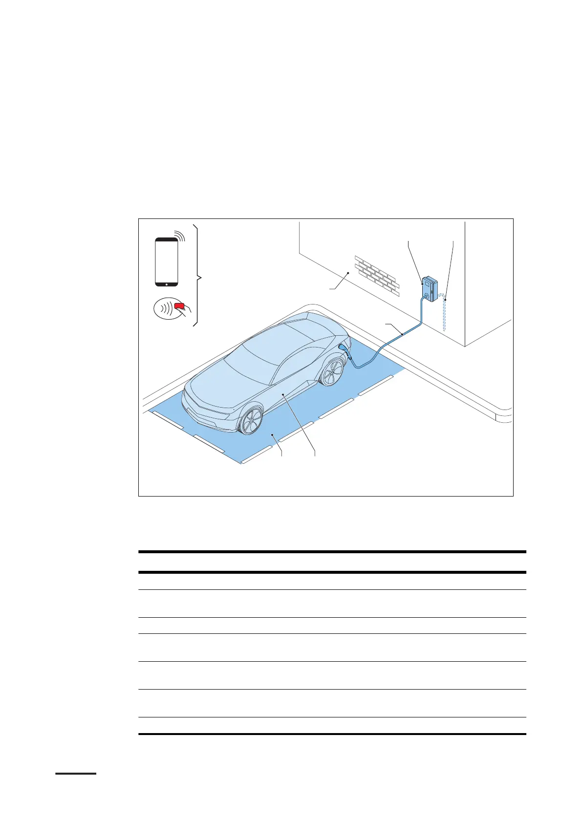
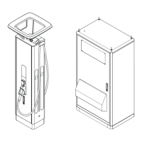
2.5 Overview
2.5.1 Overview of the system
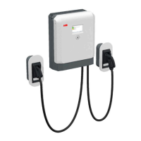
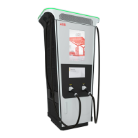
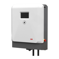
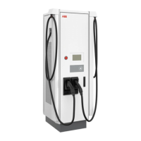
A EVSE
B AC grid input
C EV
D Parking space
E RFID card or smartphone
F Structure to install the EVSE on
G EV charge cable
Part Function
EVSE Refer to section
2.2
.
Structure To install the EVSE on and to keep the
EVSE in position.
AC grid input To supply the electricity to the EVSE
EV charge cable To conduct the charge from the EVSE to
the EV
EV The EV of which the batteries need to be
charged
Parking space Location for the EV during the charge ses-
sion
RFID card or smartphone To authorize the user to use the EVSE
Description
14 BCM.V3Y01.0-EN | 001