EasyManuals Logo

Acer Aspire V5-571 User Manual

Acer Aspire V5-571
230 pages
To Next Page IconTo Next Page
To Previous Page IconTo Previous Page
Page #83 background imageLoading...
Page #83 background image
Machine Maintenance 3-7
Disassembly Process 0
The disassembly process is divided into the following stages:
External Module Disassembly
Main Unit Disassembly
LCD Module Disassembly
The flowcharts provided in the succeeding disassembly sections illustrate the entire
disassembly sequence. Observe the order of the sequence to avoid damage to any of the
hardware components. For example, if you want to remove the main board, you must first
remove the keyboard, then disassemble the inside assembly frame in that order.
Table 3-1. Main Screw List
Screw Quantity Acer Part Number
M2 x L3 10 86.9A552.3R0
M2 x L3 (black) 10 86.00J40.323
M2.5 x L5 27 86.00J51.535
M2 x 3 1 -
Thermal Screw 5 N/A

Table of Contents

Questions and Answers:

Question and Answer IconNeed help?

Do you have a question about the Acer Aspire V5-571 and is the answer not in the manual?
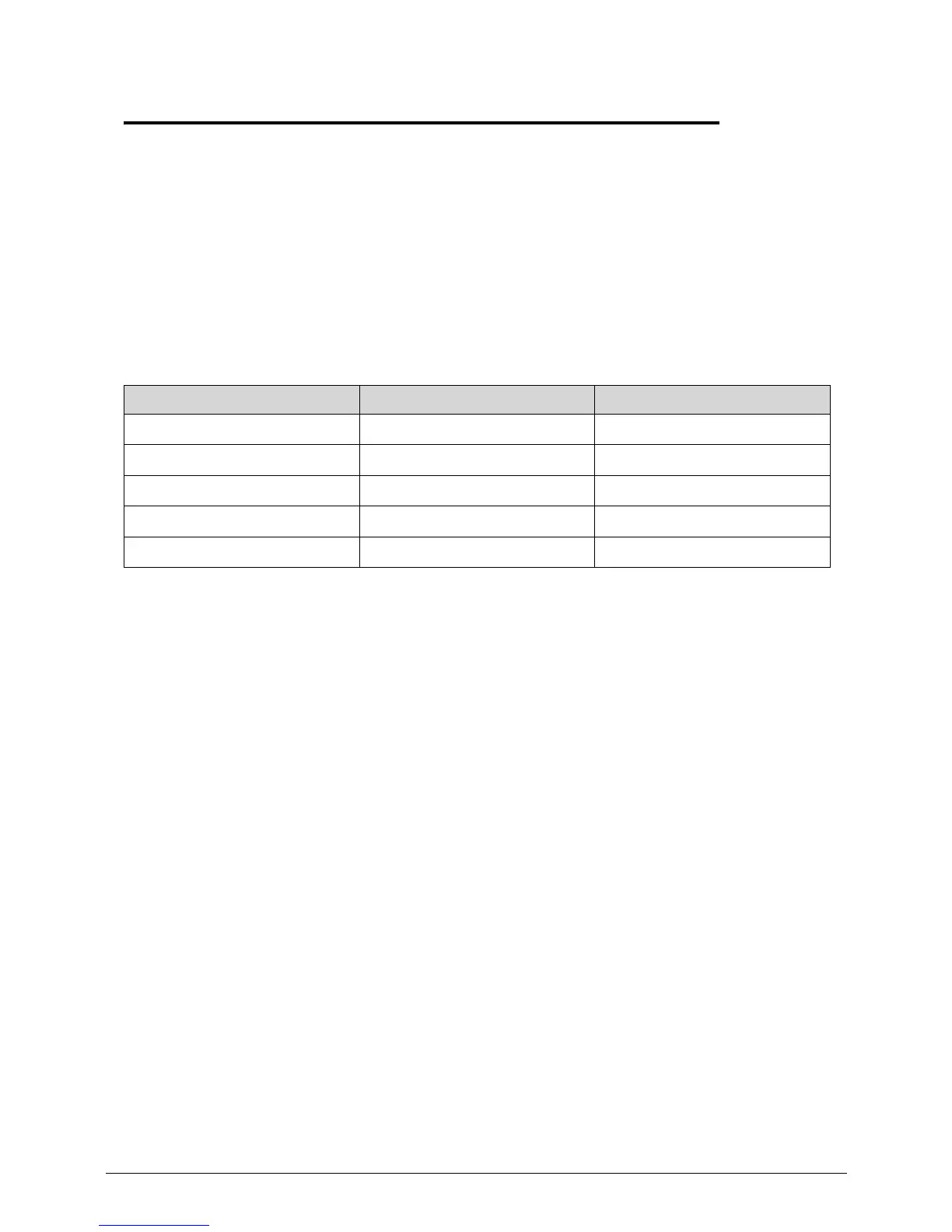
Acer Aspire V5-571 Specifications

General IconGeneral
GraphicsIntel HD Graphics 4000
Operating SystemWindows 8
ProcessorIntel Core i3/i5/i7 (depending on model)
RAM4GB DDR3
Storage500GB HDD
Display15.6-inch HD (1366 x 768)
Battery4-cell Li-ion battery
Weight2.3 kg
Ports2 x USB 2.0, 1 x USB 3.0, HDMI, Ethernet
Wireless802.11b/g/n
WebcamHD webcam

Related product manuals