52
GB
4598010_00
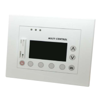
The fi fth window of the SYSTEM SETUP allows the user
to check the status of the network linked to the MULTI
CONTROL; this window displays the following information:
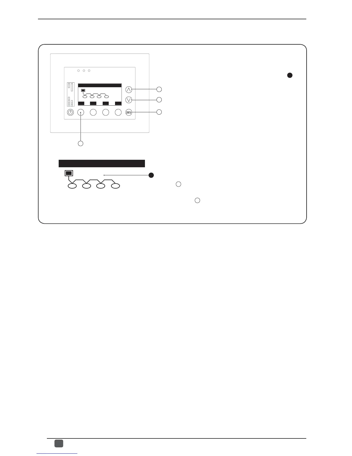
- Graphic on the situation of the serial network (
1
):
indicates the elements of the system and their communication;
the network graphic is generated depending on that set by
the installer in the various menus (number of units installed
and number of VMF CRP modules installed); the user can
also check the status of communication based on the symbol
displayed above the words (no symbol means there is no
communication and there is probably an error in progress;
if an ellipse is displayed, it means that communication is
correct); the following words can be displayed:
- U1 (Unit 1).
- U2 (Unit 2).
- U3 (Unit 3).
- U4 (Unit 4).
- E1 (Additional VMF CRP 1 module).
- E2 (Additional VMF CRP 2 module).
- E3 (Additional VMF CRP 3 module).
From this window it is possible to:
(1) Go back to the previous window:
to go back to the previous window of this menu, press the
key
A
.
(2) Exit this window:
press the key
D
to return to the selection of the USER menus.
• Viewing network status (Password 101 or 303):
A
B
C
ESC
D
1
RS485 status
U1 U2 E1 E2
RS485 status
U1 U2 E1 E2
 Loading...