Publication 1747-UM006B-EN-P - June 2003
8-2 Application Examples
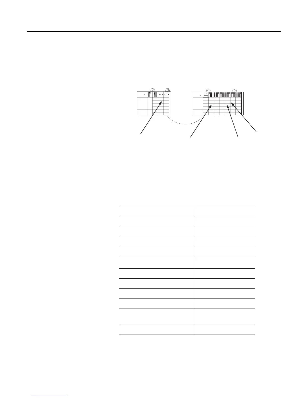
The application is illustrated below. When the switch is closed, bulbs
1 and 2 turn on and an analog signal is moved to analog module
output 1, which leads to the meter.
RIO Device Configuration
The 1747-ASB module is configured in the following manner.
SLC 5/02
17461-OW8
1746-NIO4I
1747-SN
ASB
1746-OA16
1746-IA16
012 3
01 234 56
1746-IA16
1746-IA16
1746-OA16
1746-OA16
The meter is connected
to output 1.
The switch is connected
to input 15.
Bulb 2 is connected to
output 12.
Bulb 1 is
connected to
output 4.
Function 1747-ASB Module 1
Starting logical rack number 0
Starting logical group number 0
Image size (number of logical groups) 6
Addressing mode 1-slot
Specialty I/O mode
(1)
Discrete
Baud rate 230.4K
Last chassis Yes
Hold last state Yes
Processor restart lockout Yes
Link response
(2)
Switch position does not
matter
Primary/complementary chassis Complementary
(1) The 1747-SN Series A scanner cannot perform block transfers. Any specialty I/O modules
controlled by this scanner must be discretely mapped.
(2) Link response does not matter at 230.4K baud.
Artisan Technology Group - Quality Instrumentation ... Guaranteed | (888) 88-SOURCE | www.artisantg.com

 Loading...


