Publication 1747-UM006B-EN-P - June 2003
8-20 Application Examples
1747-ASB Module 2 Configuration Details
Because the image of 1747-ASB module 2 does not cross a logical rack
boundary, 1747-ASB module 2 appears as one logical device to the
scanner.
1747-ASB module 2 is configured for last chassis because it has the
highest logical group (group 5) in its highest numbered logical rack
(logical rack 3).
1747-ASB module 2 is not configured for hold last state and processor
restart lockout. If the RIO communications cable is removed and
reconnected during normal RIO communications, the discrete outputs
are reset and the 1747-ASB module automatically resumes
communicating with the PLC-5/40.
1747-ASB module 2 is configured as a complementary chassis.
Because complementary I/O is not being used, there is no need for a
primary chassis.
The 1747-ASB module 2 response time is unrestricted because the
PLC-5/40 does not require a restricted response time.
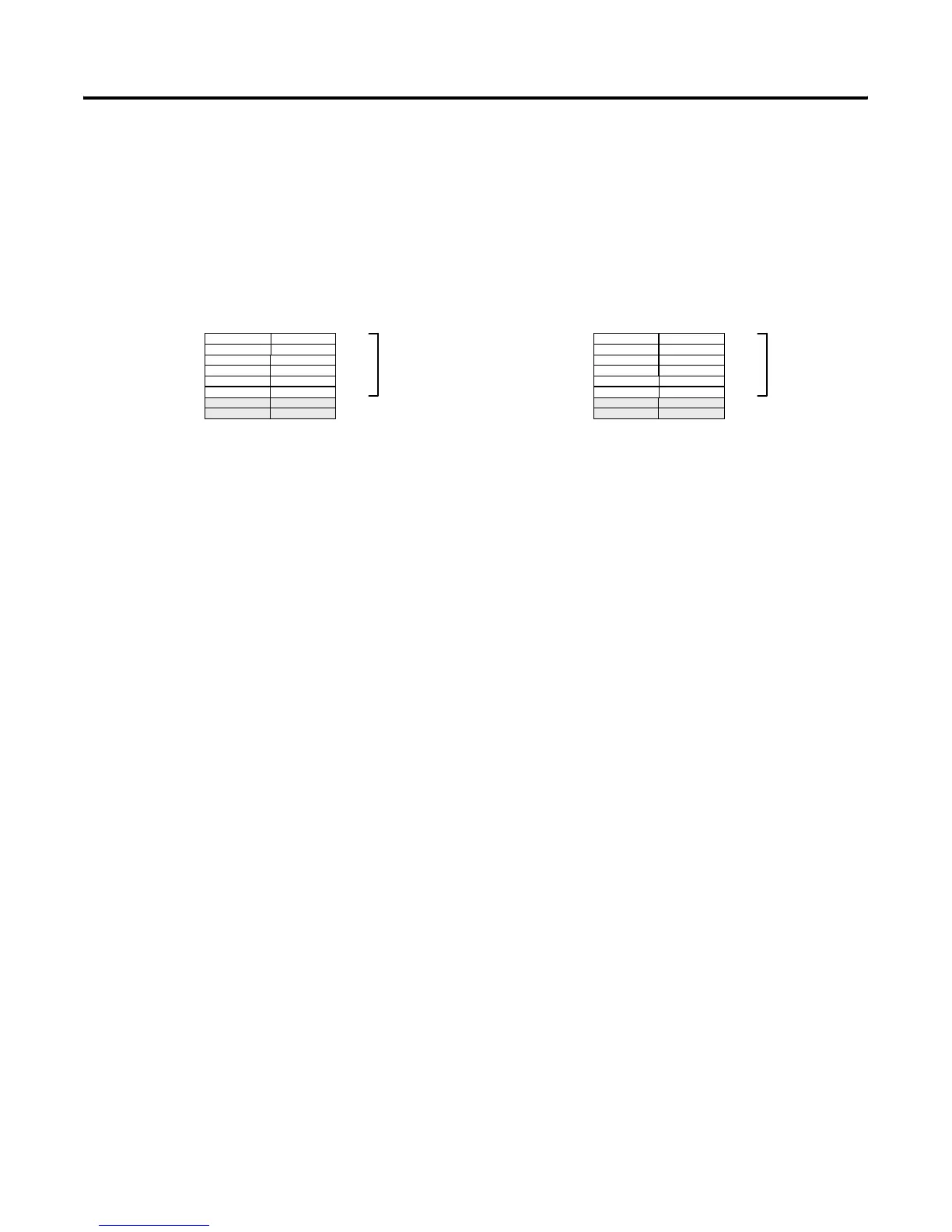
PLC Processor Input Image PLC Processor Output Image
Bit Number Octal
071017
Bit Number Octal
071017
Logical
Rack 3
I:030
I:031
I:032
I:033
I:034
I:035
I:036
I:037
Group 0
Group 1
Group 2
Group 3
Group 4
Group 5
Group 6
Group 7
Logical
Rack 3
O:030
O:031
O:032
O:033
O:034
O:035
O:036
O:037
Group 0
Group 1
Group 2
Group 3
Group 4
Group 5
Group 6
Group 7
1747-ASB
Module 2
Not Used
Not Used
NO4INO4I
NO4INO4I
NO4INO4I
NO4INO4I
1747-ASB
Module 2
Not Used
Not Used
NIO4INIO4I
NIO4INIO4I
NIO4INIO4I
NIO4INIO4I
NI4NI4
NI4NI4
NI4NI4
NI4NI4
Artisan Technology Group - Quality Instrumentation ... Guaranteed | (888) 88-SOURCE | www.artisantg.com

 Loading...


