Publication 1747-UM006B-EN-P - June 2003
Addressing 3-7
1-Slot Addressing
When the 1747-ASB module is configured for 1-slot addressing, the
processor addresses one chassis slot as one logical group. Each slot,
beginning with slot one, is sequentially assigned one word (16 bits) of
the 1747-ASB module's input and output image. Each terminal on the
I/O module is assigned a bit within the word, beginning with the least
significant bit. One-slot addressing is primarily designed to
accommodate I/O modules whose image size is less than or equal to
one word but more than one byte.
To accommodate modules that require up to two words (32 bits) of
input and/or output image, the 1747-ASB module pairs slots
beginning with slot 1 (i.e., slot 1 paired to slot 2, etc.). Slot pairing
combines both words (of either the input or output image, whichever
is required) and assigns them to one slot. This maximizes I/O image
space, allowing you to install an input module in one slot and an
output module in the other, each using up to 32 bits of the paired
input and output images.
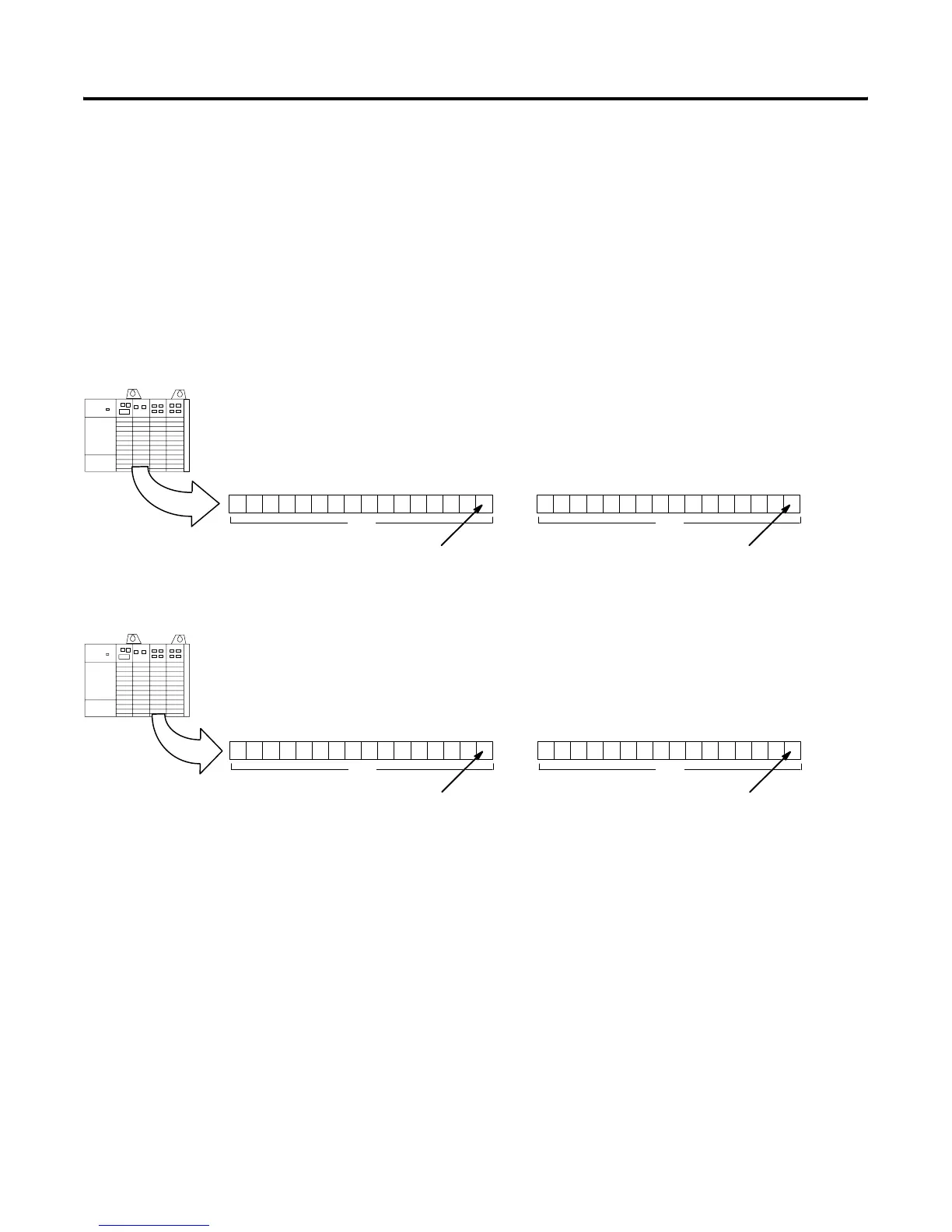
Slot 1
Slot 1 is assigned to the first logical group of the 1747-ASB
module’s image, beginning with bit 0 (the LSB).
Slot 1
151413121110987 6543 210
Slot 2
Each terminal is assigned a bit,
beginning with the least significant bit.
group 0
Slot 2
1514131211109876 543 210
Each terminal is assigned a bit,
beginning with the least significant bit.
group 1
Slot 2 is assigned the next logical group of the 1747-ASB
module’s image, beginning with bit 0 (the LSB).
Decimal
Octal701017
Input Image
Slot 1
1514131211109876 5432 10
Each terminal is assigned a bit,
beginning with the least significant bit.
group 0
Decimal
Octal701017
Output Image
Decimal
Octal701017
Input Image
Slot 2
15141312111098765 432 10
Each terminal is assigned a bit,
beginning with the least significant bit.
group 1
Decimal
Octal701017
Output Image
Artisan Technology Group - Quality Instrumentation ... Guaranteed | (888) 88-SOURCE | www.artisantg.com

 Loading...


