Publication 1747-UM006B-EN-P - June 2003
5-2 Installation and Wiring
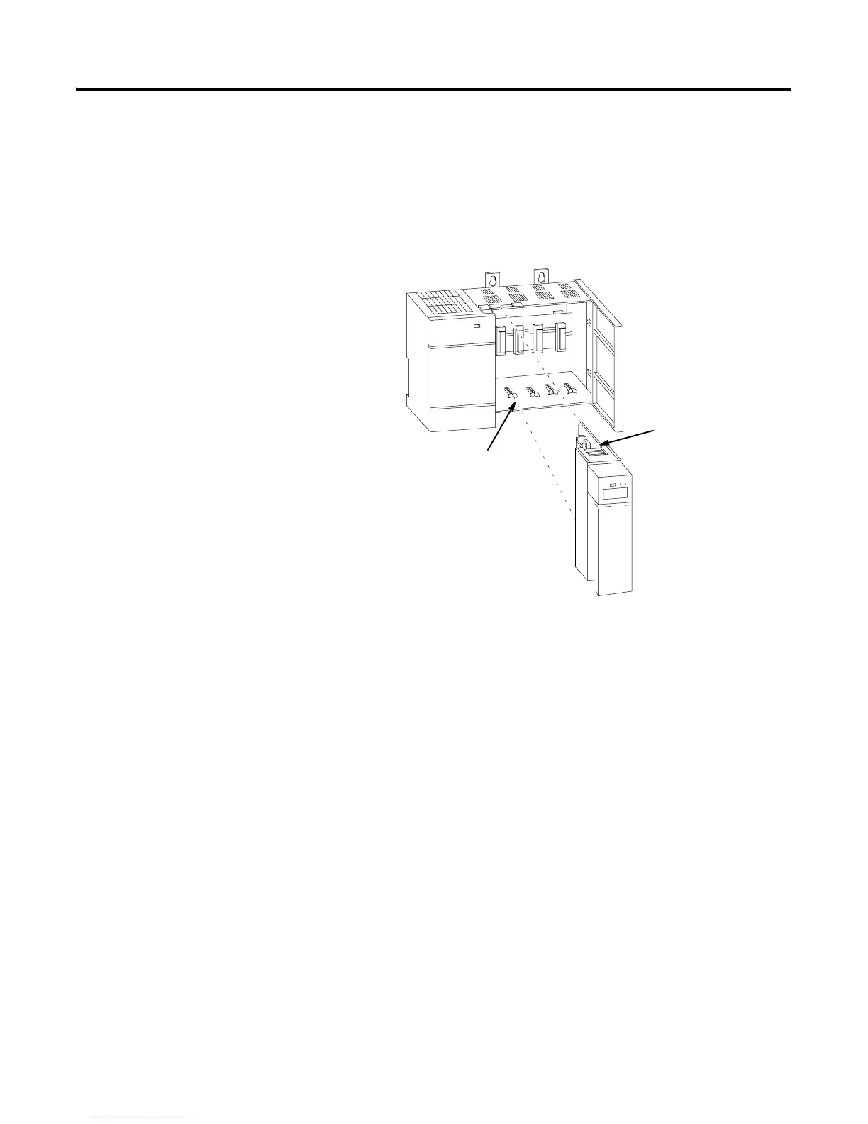
2. Slide the module into the chassis until the top and bottom tabs
lock into place. To remove the module, press and hold the
release located on each self-locking tab and slide the module
out.
3. Cover all unused slots with the Card Slot Filler, Catalog Number
1746-N2.
The modules are connected in a daisy chain configuration on any RIO
link. A daisy chain network is formed by connecting network devices
together in a serial manner using Belden 9463 cable. Belden 9463
cable is the only approved cable for Allen-Bradley RIO links.
Link Wiring
The total number of adapters allowed on the RIO link are:
• 32 if the scanner and all adapters on the RIO link have extended
node capability
• 16 if the scanner or any adapter does not have extended node
capability
Refer to page 1-8 for information on extended node capability.
There are no restrictions governing the spacing between the devices,
as long as the maximum cable distance is not exceeded. Refer to the
table below for baud rate and maximum cable distances.
Card Guide
Module Release
Artisan Technology Group - Quality Instrumentation ... Guaranteed | (888) 88-SOURCE | www.artisantg.com

 Loading...


