Publication 1747-UM006B-EN-P - June 2003
4-22 Configuration
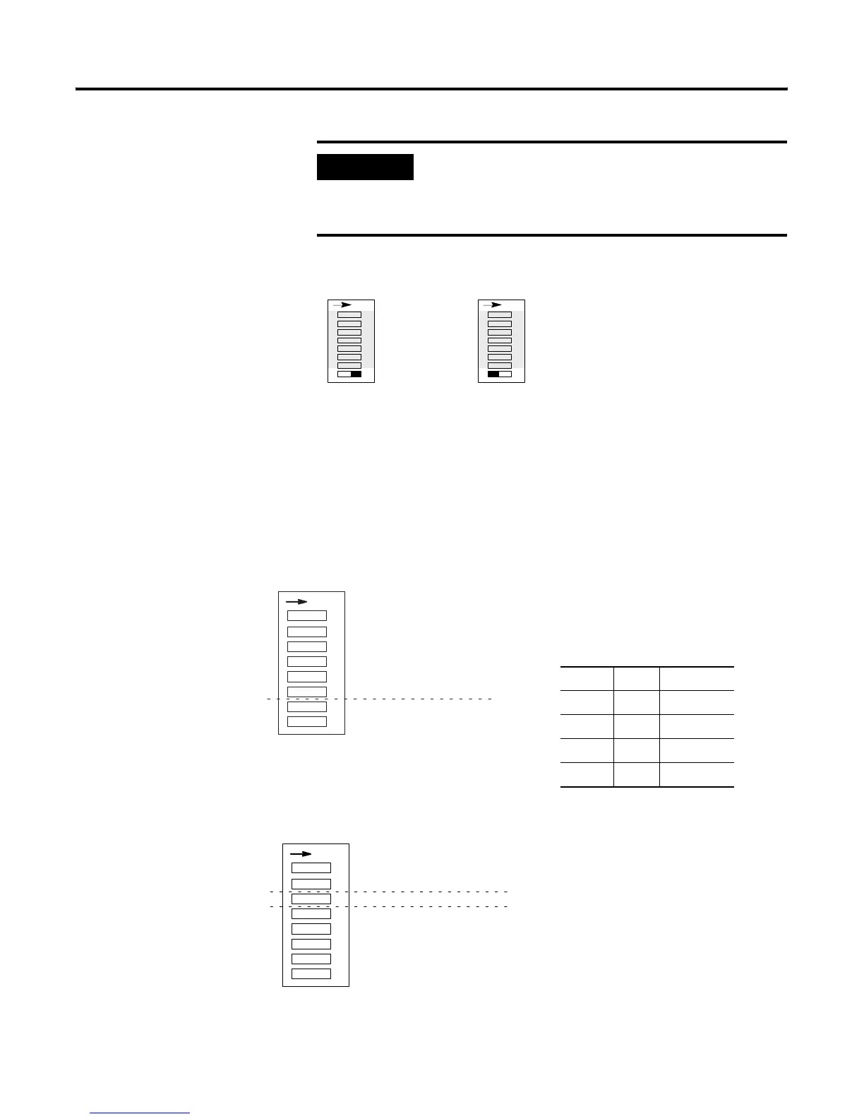
I/O Module Keying DIP Switch Settings
The 1747-ASB module is shipped from the factory with the default
position ON (save mode).
Switch Setting Summary
The following is a summary listing the various DIP switch settings.
IMPORTANT
Use save mode during setup and debug. After
debugging is complete, power up in save mode one
last time. Remove power and place the 1747-ASB
module in check mode prior to normal operation.
SW3
Save Mode
41 23 5678
O
N
SW3
Check Mode
41 23 5678
O
N
SW1
• Logical Rack Number
For details, see page 4-2.
• Logical Group Number
SW2
• Baud Rate
• Primary/Complementary Chassis
ON=Primary
OFF=Complementary (default)
• 1747-ASB Module Image Size
For details, see page 4-9.
1
O
N
2456783
SW1
Logical Rack Number Bit 5 (MSB)
Logical Rack Number Bit 4
Logical Rack Number Bit 3
Logical Rack Number Bit 2
Logical Rack Number Bit 1
Logical Rack Number Bit 0 (LSB)
Logical Group Number Bit 1 (MSB)
Logical Group Number Bit 0 (LSB)
78Group
ON ON 0 (default)
ON OFF 2
OFF ON 4
OFF OFF 6
SW2
1
O
N
2456783
Baud Rate Bit 1 (MSB)
Baud Rate Bit 0 (LSB)
Primary/Complementary Chassis
Reserved
ASB Module Image Size Bit 3 (MSB)
ASB Module Image Size Bit 2
ASB Module Image Size Bit 1
ASB Module Image Size Bit 0 (LSB)
Artisan Technology Group - Quality Instrumentation ... Guaranteed | (888) 88-SOURCE | www.artisantg.com

 Loading...


