Publication 1747-UM006B-EN-P - June 2003
8-12 Application Examples
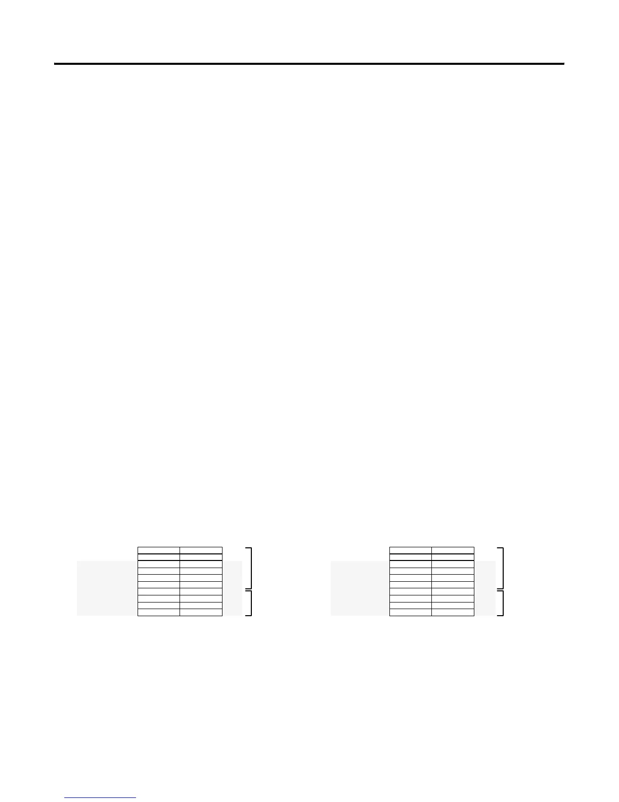
1747-ASB Module 1 I/O Mapping Details
Because 1747-ASB module 1 is configured for 1-slot addressing, has
six logical groups and six slots available for I/O, all of the slots
present are mapped into the scanner image. No extra slots in the
chassis, or extra words in the image remain.
Because the specialty I/O mode chosen is discrete mode and the
1747-ASB module is configured for 1-slot addressing, all specialty
modules that have two words or less of input and output image are
discretely mapped.
The 1746-NIO4I module requires two input and two output words.
Therefore, it is discretely mapped. When 1-slot addressing is selected,
two words of input image and two words of output image are
available for each slot pair. Because it requires both words of the
input and output image, slot 2 must remain empty. If an I/O module is
inserted into slot 2, a 1747-ASB module error occurs.
Due to slot pairing, two 32-point modules that have opposite
functions (one input and one output), are allowed in one slot pair
using 1-slot addressing. The 32-point input module, Catalog Number
1746-IV32, installed in slot 3 uses the input image words assigned to
slots 3 and 4. No input image is available for slot 4. Slot 4 can use the
output image that slot 3 is not using. Therefore, a 32-point output
module, Catalog Number 1746-OV32 uses the output image assigned
to slots 3 and 4.
Slots 5 and 6 contain 16-point output modules. The input words
assigned to these slots are not used.
1747-ASB Module 2 I/O Mapping Details
Because 1747-ASB module 2 is configured for 2-slot addressing, has
two logical groups and three slots available for I/O, all of the slots
present are mapped into the scanner image. One extra byte of input
Bit Number (Decimal)
07815
Logical
Rack 2
SLC Processor Input Image
I:3.14
I:3.15
I:3.16
I:3.17
I:3.18
I:3.19
I:3.20
I:3.21
I:3.22
I:3.23
Group 6
Group 7
Group 0
Group 1
Group 2
Group 3
Group 4
Group 5
Group 6
Group 7
1747-ASB
Module 1
RediPANEL
NIO4I
NIO4I
NIO4I
NIO4I
IV32
IV32
IV32
IV32
Bit Number (Decimal)
07815
Logical
Rack 2
SLC Processor Output Image
O:3.14
O:3.15
O:3.16
O:3.17
O:3.18
O:3.19
O:3.20
O:3.21
O:3.22
O:3.23
Group 6
Group 7
Group 0
Group 1
Group 2
Group 3
Group 4
Group 5
Group 6
Group 7
1747-ASB
Module 1
RediPANEL
NIO4I
NIO4I
NIO4I
NIO4I
OV32
OV32
OV32
OV32
OB16 OB16
OA16OA16
Artisan Technology Group - Quality Instrumentation ... Guaranteed | (888) 88-SOURCE | www.artisantg.com

 Loading...


