Publication 1747-UM006B-EN-P - June 2003
8-4 Application Examples
The default configuration size of the scanner image is 32 words. You
can specify that the SLC 5/02 processor scan is less than 32 words
with your programming device.
1747-ASB Module Configuration Details
The entire image of the 1747-ASB module is contained in logical
rack 0. It does not cross a logical rack boundary. Therefore, it appears
as one logical device to the scanner.
The 1747-ASB module is configured as the last chassis because it uses
the highest numbered logical group in the highest logical rack it
resides in.
The 1747-ASB module is configured for hold last state and processor
restart lockout. If the RIO communications cable is removed and
reconnected during normal RIO communications, the discrete outputs
remain in their last state and the 1747-ASB module does not resume
communicating with the scanner, until the processor restart lockout
terminals are momentarily shorted together. For more information
regarding processor restart lockout, refer to chapter 4.
The 1747-ASB module is configured as a complementary chassis.
Because complementary I/O is not being used, there is no need for a
primary chassis.
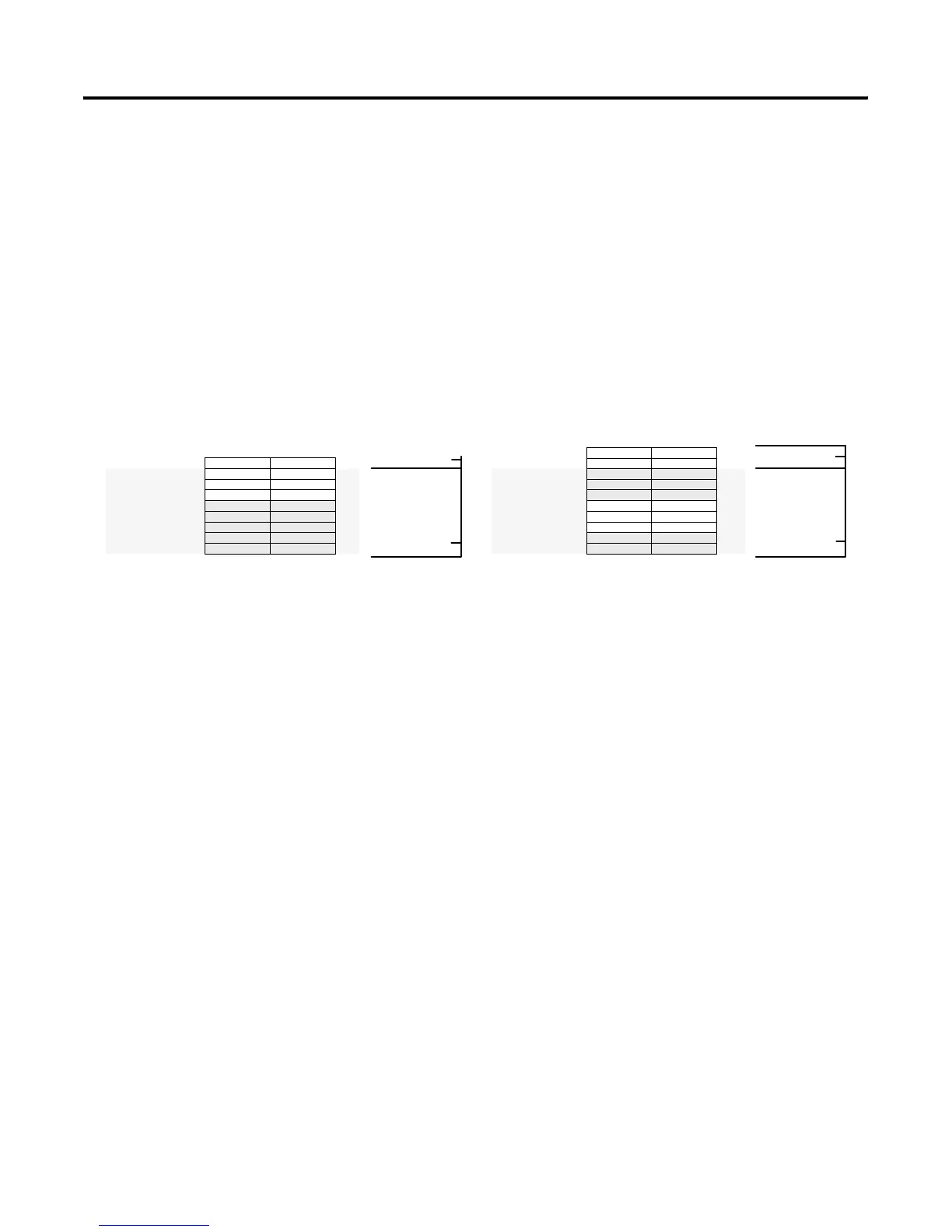
1747-ASB Module I/O Mapping Details
The 1747-ASB module is configured for 1-slot addressing. Its image
starts at group 0 of logical rack 0 and is sized for six logical groups.
There are six 16-bit words of input and output image for its three
16-point input and output modules.
Bit Number (Decimal)
07815
Logical
Rack 0
SLC Processor Input Image
Local SLC Chassis
I:2.0 & .1
I:3.0
I:3.1
I:3.2
I:3.3
I:3.4
I:3.5
I:3.6
I:3.7
Group 0
Group 1
Group 2
Group 3
Group 4
Group 5
Group 6
Group 7
NIO4INIO4I
Bit Number (Decimal)
07815
Logical
Rack 0
SLC Processor Output Image
Local SLC Chassis
O:2.0 & .1
O:3.0
O:3.1
O:3.2
O:3.3
O:3.4
O:3.5
O:3.6
O:3.7
Group 0
Group 1
Group 2
Group 3
Group 4
Group 5
Group 6
Group 7
OW8OW8
OA16OA16
IA16
Scanner Image Scanner Image
Not Used
Not Used
Not Used
Not Used
Not Used
Not Used
Not Used
IA16
Not Used
IA16 IA16
IA16 IA16
OW8
NIO4INIO4I
Not Used
Not Used
OA16OA16
OA16OA16
O:1.0
remote slot 1
remote slot 2
remote slot 3
remote slot 4
remote slot 5
remote slot 6
remote slot 1
remote slot 2
remote slot 3
remote slot 4
remote slot 5
remote slot 6
Artisan Technology Group - Quality Instrumentation ... Guaranteed | (888) 88-SOURCE | www.artisantg.com

 Loading...


