Publication 1747-UM006B-EN-P - June 2003
Application Examples 8-15
Application Example Program
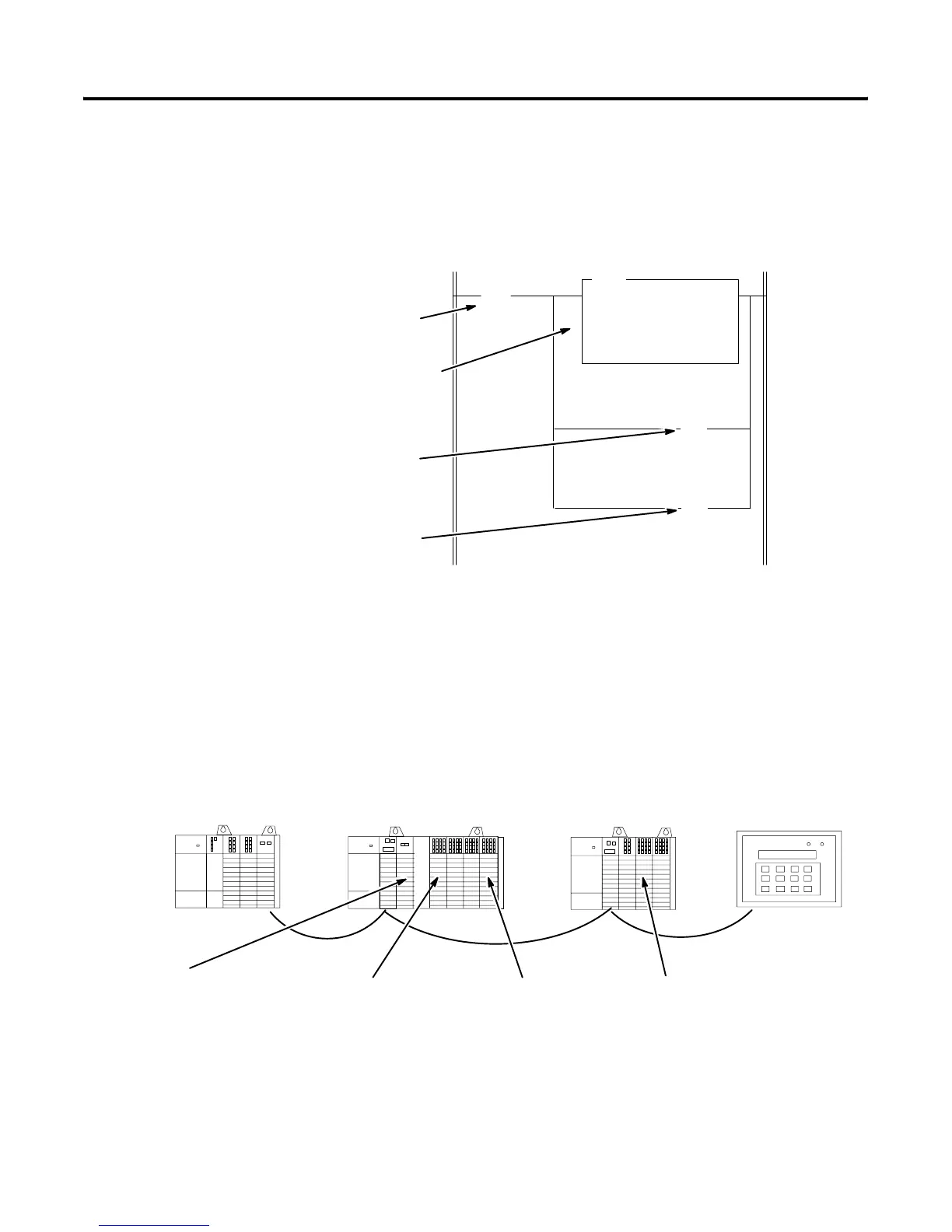
Shown below is an excerpt from the user program. When the switch is
closed, bulbs 1 and 2 turn on and the decimal value 5555 is moved to
analog output 1 and is converted to an analog signal.
The following is another representation of what is discussed above.
This application consists of a PLC-5/40 processor controlling local and
remote I/O.
] [
I:3.17
1
( )
O:3.0
MOV
MOVE
Source 5555
Dest O:3.15
12
( )
O:3.19
12
Switch
(1)
Meter
Bulb 1
(2)
Bulb 2
(1) Input bits 16–31 must be converted to 0–15 by subtracting 16. Therefore, Input bit 17 is converted to 1.
(2) Input and Output bits 0–7 must be converted to 8–15 by adding 8. Therefore, Input bit 12 is converted to 4.
012 3
01 234 56
012 3
SLC 5/02
1746-OW8
1746-IA8
1747-SN
ASB 1
1746-NIO4I
1746-IV32
1746-OV32
1746-OB16
1746-OA16
ASB 2
1746-OA8
1746-IO12
1746-IA16
EMPTY
RediPANEL
The meter is connected
to output 1.
The switch is connected
to input 17.
Bulb 2 is connected
to output 12.
Bulb 1 is connected
to output 4.
Artisan Technology Group - Quality Instrumentation ... Guaranteed | (888) 88-SOURCE | www.artisantg.com

 Loading...


