Publication 1747-UM006B-EN-P - June 2003
Addressing 3-5
To accommodate modules that require up to one word (16 bits) of
input and/or output image, the 1747-ASB module pairs slots
beginning with slot 1 (i.e., slot 1 is paired to slot 2, etc.). Slot pairing
combines the low and high byte into a one word input and output
image. This maximizes I/O image space, allowing you to install an
input module in one slot and an output module in the other, each
using up to 16 bits of the paired input and output images.
2-Slot Addressing Considerations
When the 1747-ASB module is configured for 2-slot addressing, you
can use 4-, 8-, 16-point, combination, and specialty I/O modules.
If it is necessary to use 16-point modules, like modules (i.e., two input
modules) cannot be installed as a pair. This is because each 16-point
module uses a full word in the image. For this reason you must pair
an input with an output module. 32-point modules cannot be used.
If the discrete mode is selected, specialty I/O modules with one word
or less of input and output image are discretely mapped such as the
1747-KE. Specialty I/O modules with two or more words of input or
output image are block transfer mapped.
If block transfer mode is selected, all specialty I/O modules are block
transfer mapped regardless of their image size.
The 1747-ASB module can block transfer map a maximum of eight
words.
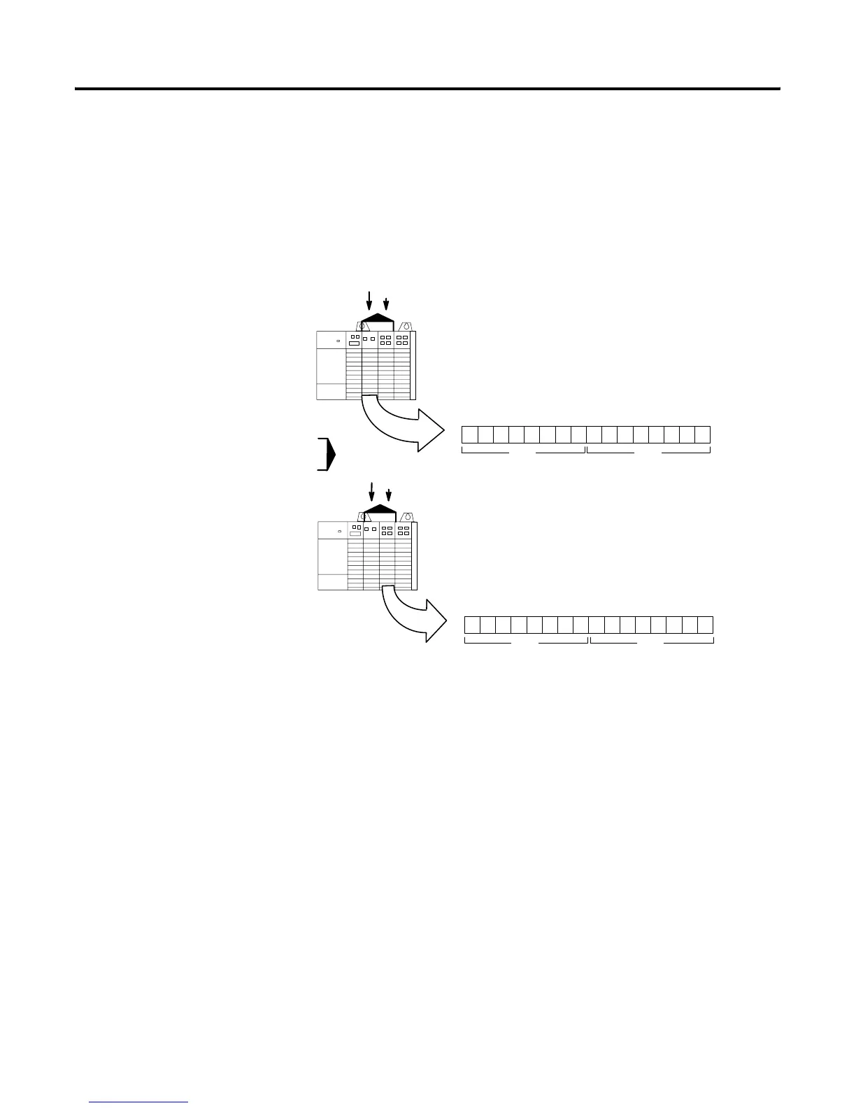
Slot 1
Paired
When a module is installed in slot 1 that requires one word of
input image, slot 1 uses the input image normally assigned to
slots 1 and 2. Slot 2, therefore, cannot use any of its input
image. However, slot 2 can now use the output image
normally assigned to slots 1 and 2, because slot 1 is not
using its portion of the output image.
Slot 1Slot 1
Slot 2
Paired
When a module is installed in slot 2 that requires one word of
output image, slot 2 uses the output image normally
assigned to slots 1 and 2 (if slot 1 is not already using it).
The lesser slot number has priority over the greater.
Slot 2Slot 2
Group 0
Group 0
1514131211109876 5432 10
701017
Decimal
Octal
15141312111098765 432 10
701017
Decimal
Octal
O
I = Input Module
= Output Module
I
O
I
O
Slot Pair
Input Image
Output Image
Artisan Technology Group - Quality Instrumentation ... Guaranteed | (888) 88-SOURCE | www.artisantg.com

 Loading...


