 Loading...
Do you have a question about the Allen-Bradley 1756-L61 and is the answer not in the manual?
| Brand | Allen-Bradley |
|---|---|
| Model | 1756-L61 |
| Category | Controller |
| Language | English |
Explains safety symbols (WARNING, ATTENTION, etc.) and their meanings.
Details topics revised or added in the current manual revision.
Provides an overview of controller types: Traditional, Extreme Environment, and Safety GuardLogix.
Describes the two lines of traditional ControlLogix controllers: 1756-L6x and 1756-L7x.
Notes that certain controllers support use in redundant systems.
Details extreme environment controllers and their temperature ratings.
Identifies minimum software versions required for controller use.
Lists resources for further information on ControlLogix controllers and systems.
Details environmental considerations and enclosure requirements for the controller.
Provides guidelines to prevent damage from electrostatic discharge.
Information for use in Zone 2 potentially explosive atmospheres as defined by EU Directive.
Warns against using the USB port in hazardous locations and specifies cable length.
Provides information for operating the equipment in hazardous locations.
Details parts included with and available for the 1756-L7x controller.
Lists parts that can be used with the 1756-L7x controller based on application needs.
Provides step-by-step instructions for inserting the controller into the chassis.
Details the procedure for safely removing the Secure Digital (SD) card.
Provides step-by-step instructions for installing the Secure Digital (SD) card.
Explains the procedure and precautions for removing the Energy Storage Module (ESM).
Details the procedure for installing the Energy Storage Module (ESM).
Lists general precautions to consider before installing or removing controllers.
Discusses environmental conditions and enclosure requirements for the controller.
Provides guidelines to prevent damage from electrostatic discharge.
Information for use in Zone 2 potentially explosive atmospheres as defined by EU Directive.
Warns against using the USB port in hazardous locations and specifies cable length.
Provides information for operating the equipment in hazardous locations.
Warns about electrical arcs during battery connection/disconnection.
Details parts included with the 1756-L6x controller.
Lists parts specific to application that are not included with the controller.
Outlines the tasks required to install the 1756-L6x controller.
Details the procedure for removing a CompactFlash card from a Series A controller.
Details the procedure for installing a CompactFlash card in a Series B controller.
Details the procedure for removing a CompactFlash card from a Series B controller.
Provides information on battery replacement and handling.
Presents a schedule for replacing batteries based on temperature.
Provides instructions for installing a 1756-BA1 battery on a Series A controller.
Provides instructions for installing a 1756-BA2 battery on a Series B controller.
Provides step-by-step instructions for inserting the controller into the chassis.
Details the procedure for removing the controller from the chassis.
Explains the necessity of making a connection to the controller before use.
Outlines the connection options available for the 1756-L7x controller.
Outlines the connection options available for the 1756-L6x controller.
Explains how to connect to the 1756-L7x controller using a USB port.
Details the procedure to set up the USB driver for RSLinx software.
Explains how to connect to the 1756-L6x controller using a serial port.
Guides on configuring the RS232 DF1 device driver in RSLinx software.
Introduces tools for upgrading controller firmware: ControlFLASH and AutoFlash.
Provides a table to determine the required firmware revision for controllers.
Outlines steps to upgrade controller firmware using the ControlFLASH utility.
Details steps to upgrade controller firmware using the AutoFlash feature.
Explains how to specify the communication path in RSLogix 5000 software.
Describes methods to establish an online connection with the controller.
Explains how to move a project from RSLogix 5000 software to the controller.
Describes how to copy a project from the controller to RSLogix 5000 software.
Uses a table as reference for determining controller operation modes.
Explains how to use the physical mode switch to change controller operation mode.
Describes changing controller operation mode via RSLogix 5000 software.
Explains loading or storing user memory contents to the compatible memory card.
Details using ESMs to provide power to controllers for saving programs.
Provides steps to save the program to NVS memory when controller loses power.
Provides a table to estimate ESM hold-up time based on temperature.
Explains how to monitor and maintain lithium batteries supported by controllers.
Describes low-battery warnings indicated by BAT status.
Details using the 1756-BATM module with 1756-L6x Series A controllers.
Provides a table to estimate 1756-BA2 battery life before becoming low.
Estimates battery life after low-battery warnings are indicated.
Provides general rules for storing and disposing of batteries.
Describes the chassis-based system and its capabilities.
Outlines various system configuration options available for ControlLogix controllers.
Explains connecting various devices via multiple communication networks.
Discusses system components to consider when designing a ControlLogix system.
Lists system, communication, and programming features of ControlLogix controllers.
Helps determine controller needs based on user memory availability.
Lists typical network applications and supported networks for ControlLogix systems.
Provides an overview of EtherNet/IP network services and components.
Lists EtherNet/IP modules and their primary features for ControlLogix systems.
Explains how DDR communication can be achieved with specific communication modules.
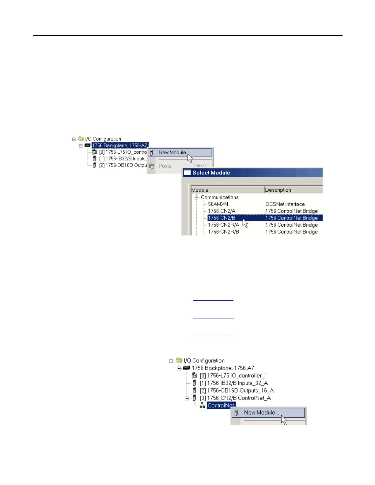
Lists features of ControlLogix ControlNet communication modules.
Lists software used with ControlNet networks and modules.
Explains how to determine connection numbers for ControlNet networks.
Describes DeviceNet network capabilities and technology.
Lists features of ControlLogix DeviceNet communication modules.
Lists DeviceNet bridge modules and linking devices.
Details connection requirements for the 1756-DNB DeviceNet module.
Describes memory sections for input/output data of DeviceNet devices.
Provides information about DH+ network communication.
Lists module options for universal remote I/O communication.
Describes Foundation Fieldbus for process control instrumentation.
Describes HART communication protocol for process control.
Describes the built-in RS-232 port on 1756-L6x controllers for serial applications.
Guides on specifying serial port mode and protocol for communication.
Explains the DF1 Point to Point protocol for connecting to a single DF1 device.
Details the driver for communicating over DF1 radio modem protocol.
Highlights the advantages of using the DF1 radio modem protocol for efficiency.
Lists considerations for implementing the DF1 radio modem driver.
Provides a table for setting DF1 Radio Modem protocol parameters.
Explains the DF1 Slave protocol using half-duplex communication.
Describes sending and receiving messages over a DH-485 network.
Guides on configuring the 1756-L6x controller's serial port for communication.
Explains using ASCII protocol for reading/sending characters from devices.
Details broadcasting messages to slave controllers via serial port.
Outlines steps to configure serial port properties in System Protocol.
Explains how to add and configure the Message instruction for communication.
Explains how Logix5000 systems establish communication links between devices.
Describes how ControlLogix controllers produce and consume system-shared tags.
Explains using MSG instruction to transfer data to other devices.
Guides on choosing whether to cache connections for MSG instructions.
Provides a table to calculate the number of local connections based on chassis configuration.
Advises on selecting I/O modules, considering variety and features.
Lists available ControlLogix chassis and their slot counts for local I/O.
Defines remote I/O and networks used to connect it to the controller.
Describes distributed I/O located remote from controller, not specific to it.
Details reconfiguring an I/O module via Module Properties or a MSG instruction.
Explains adding I/O and devices to configuration while online in Run mode.
Lists ControlLogix modules and devices that can be added while online.
Provides a flowchart to determine when producers send data.
Notes controller support for digital and analog interfaces for motion.
Outlines general steps for configuring a motion application.
Lists methods to obtain axis information, such as using GSV/SSV instructions.
Describes motion control instructions provided for axes.
Lists elements of a control application requiring planning for execution.
Explains using multiple tasks to schedule and prioritize program execution.
Describes task priority levels and how the operating system uses them.
Explains how programs group data and logic, with routines for executable code.
Differentiates scheduled programs from unscheduled ones within tasks.
Defines routines as sets of logic instructions in a single programming language.
Explains using tags (alphanumeric names) to address data variables.
Lists the programming languages supported by the ControlLogix controller.
Describes designing and configuring sets of commonly used instructions.
Explains using GSV and SSV instructions to get and set controller data.
Describes how communication timeouts are detected and indicated.
Explains how system overhead time slice specifies controller's time for service communication.
Introduces PhaseManager tool for adding equipment phases to controller for code organization.
Lists the minimum software and hardware requirements for developing PhaseManager programs.
Explains how a state model defines equipment behavior and state transitions.
Lists equipment-phase relay ladder and structured text instructions.
Explains how redundancy provides system availability by switching control to secondary chassis.
Compares features of enhanced and standard redundancy systems.
Provides a procedure for building a typical redundant system.
Discusses considerations for ControlNet modules in redundant systems.
Discusses considerations for EtherNet/IP modules in redundant systems.
Explains support for IP address swapping in redundant systems for HMI communication.
Explains how redundancy affects scan time due to data synchronization.
Identifies ControlLogix catalog numbers certified for SIL2 applications per IEC standards.
States that RSLogix 5000 software is the required PADT for SIL2 applications.
Lists SIL2 configurations: fail-safe, high-availability, and fault-tolerant.
Describes fail-safe configuration where safety loop hardware is not redundant.
Details high-availability configuration using redundant chassis for increased availability.
Describes the four status indicators and scrolling display on 1756-L7x controllers.
Explains the scrolling status display messages for controller information.
Lists general status messages indicated on the controller.
Lists fault messages indicated on the status display when the controller is faulted.
Details major recoverable fault types, codes, and associated messages.
Explains the format and diagnosis of I/O faults.
Describes the RUN, FORCE, SD, and OK indicators for 1756-L7x controllers.
Details the status indicators located on the front of 1756-L6x controllers.
Explains the meaning of the RUN indicator states.
Indicates whether I/O forces are active or enabled on the controller.
Shows the status of the Secure Digital (SD) card.
Describes the OK indicator states and their meanings.
Explains electronic keying feature for comparing modules before communication.
Details Exact Match keying requiring precise attribute matching for communication.
Explains Compatible Keying where module determines communication acceptance.
Explains Disabled Keying where keying attributes are not considered.
Summarizes changes made in each revision of the manual for reference.

