Rockwell Automation Publication 1769-UM021G-EN-P - October 2015 321
Connect Power to the Series A L1 CompactLogix 5370 Controllers Appendix C
CompactLogix 5370 L1,
Series A, Controller Field
Power to I/O Devices
Connection
Complete these steps to connect field power to the CompactLogix 5370 L1 series
A controller. Series B L1 CompactLogix 5370 controllers can also be connected
to field power as instructed in this procedure.
1. Verify that the separate external 24V DC power source that powers the
CompactLogix 5370 L1 controller is not powered.
2. Verify that the external 24V DC power source that is connected to the
FP+ and FP- terminals is not powered.
3. Mount the external power supply that connects to the FP+ and FP-
terminals on a DIN rail.
The external power supply can be installed on the same DIN rail as the
controller or a separate DIN rail.
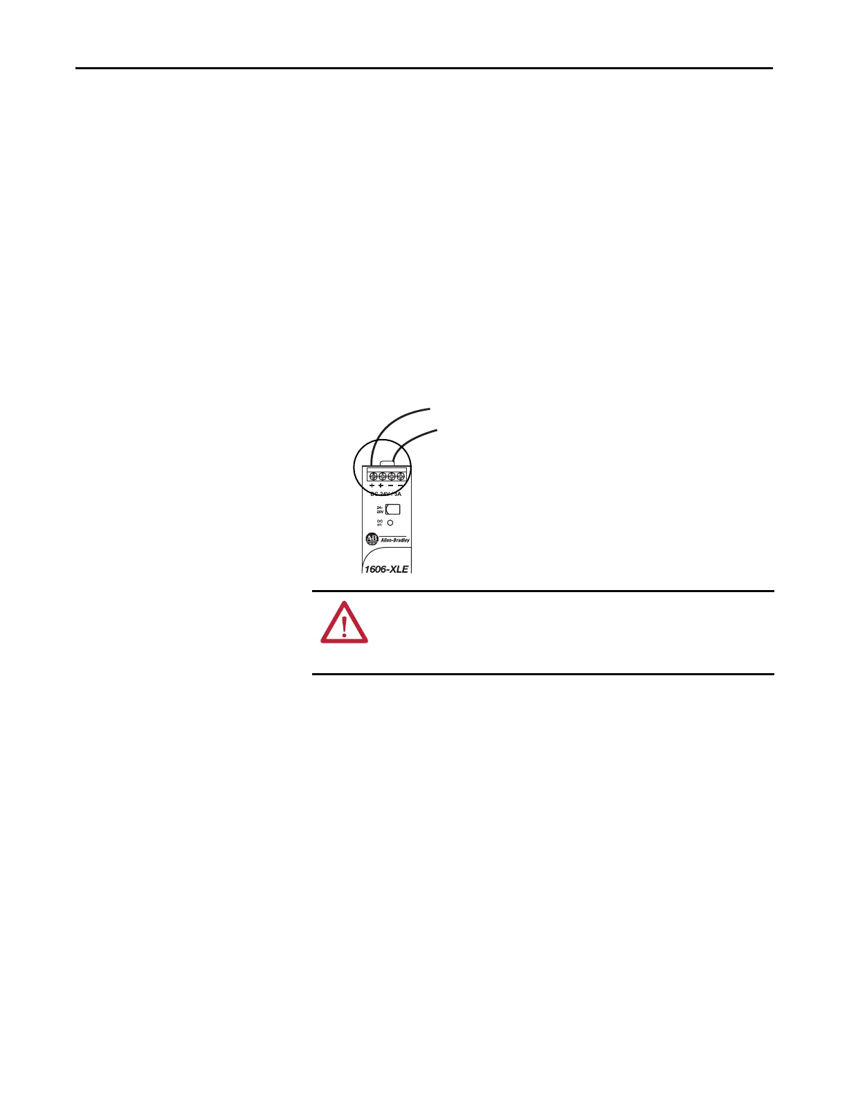
4. Connect wires to the appropriate + and - connections on the external
24V DC power source.
WARNING: If you connect or disconnect wiring while the field-side power is on,
an electrical arc can occur. This could cause an explosion in hazardous location
installations. Be sure that power is removed or the area is nonhazardous before
proceeding.