36 Rockwell Automation Publication 1769-UM021G-EN-P - October 2015
Chapter 2 Install the CompactLogix 5370 L2 Controller
Before You Begin
Consider the following before installing a CompactLogix™ 5370 L2 controller:
• The control system includes a controller, an embedded power supply,
embedded I/O points, and a 1769-ECR right end cap.
• The embedded power supply is a 24V DC input, isolated power supply
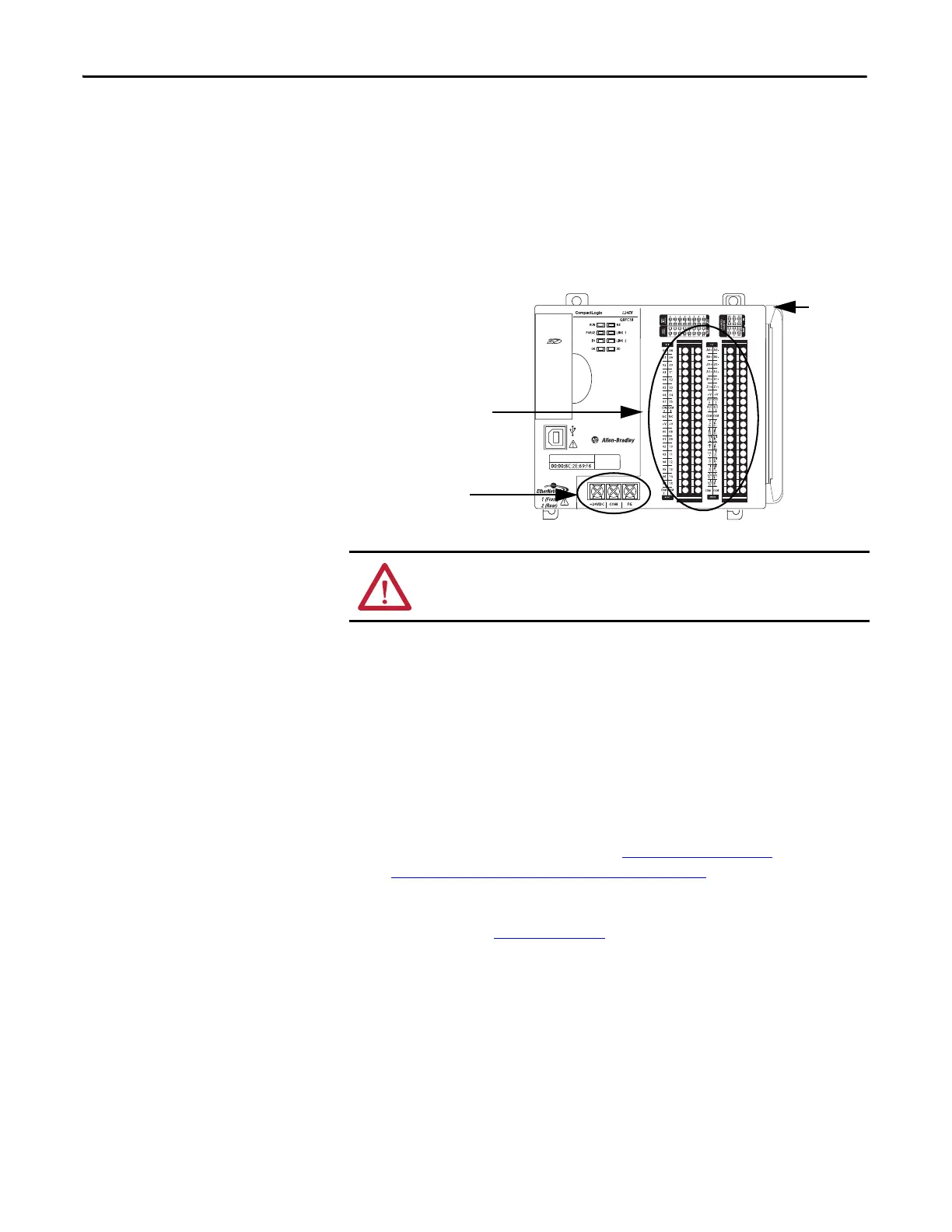
The following graphic shows an example CompactLogix 5370 L2
controller.
For example, you can use a 1606-XLSDNET4, standard switched-mode
power supply, as shown in this chapter.
• The controllers have embedded I/O points. You wire the input and output
points via a removable connector.
• The controller supports the use of up to four Compact I/O™ modules on
the local 1769 CompactBus backplane as local expansion modules.
For more information on using embedded I/O points and local
expansion modules, see Chapter 8, Use I/O Modules with
CompactLogix 5370 L2 Controllers on page 183.
• You must terminate the end of the CompactBus via a 1769-ECR right end
cap as shown in step 6 on page 47
.
• You cannot remove nor install Compact I/O modules while the controller
is powered.
ATTENTION: You must use an external power supply that is Class 2 or
SELV-listed for series A L1 controllers.
Embedded Power
Supply Terminals
Embedded I/O Modules
1769-L24ER-QBFC1B Control
End Cap

 Loading...


