EasyManuals Logo
Home>Allen-Bradley>Controller>CompactLogix 5370 L1

Allen-Bradley CompactLogix 5370 L1 User Manual

Allen-Bradley CompactLogix 5370 L1
327 pages
To Next Page IconTo Next Page
To Previous Page IconTo Previous Page
Page #318 background imageLoading...
Page #318 background image
324 Rockwell Automation Publication 1769-UM021G-EN-P - October 2015
Appendix C Connect Power to the Series A L1 CompactLogix 5370 Controllers
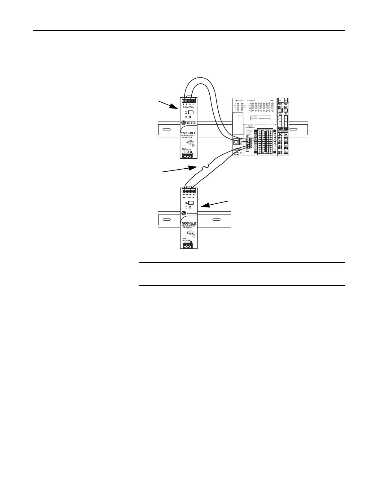
The following graphic shows separate external 24V DC power supplies
connected to the VDC+/VDC- and FP+/FP- terminals on the removable
connector, respectively.
IMPORTANT
Install a user-replaceable fuse with overcurrent protection of 4…6 A @
52.5…68.25 A
2
t in line between the incoming power and the FP+ terminal.
IMPORTANT: No wires are
connected to the NC terminal.Fuse
FP Power Supply
VDC Power Supply

Table of Contents

Other manuals for Allen-Bradley CompactLogix 5370 L1

Questions and Answers:

Question and Answer IconNeed help?

Do you have a question about the Allen-Bradley CompactLogix 5370 L1 and is the answer not in the manual?

Allen-Bradley CompactLogix 5370 L1 Specifications

General IconGeneral
BrandAllen-Bradley
ModelCompactLogix 5370 L1
CategoryController
LanguageEnglish

Related product manuals