Installing the 1203-GK5 Module or 1336-GM5 Board 3-3
Installing a 1203-GK5 Module After selecting the cables that you need, read this section for
information and instructions on installing a 1203-GK5 module.
Required Tools and Equipment
To install your 1203-GK5 module, you need the following tools and
equipment:
• DeviceNet communications module (1203-GK5).
• Either a 5-pin or 10-pin plug-in connector (supplied with
module).
• 35 x 7.5 mm DIN rail A (part 199-DR1; 46277-3; EN 50022).
• 1/8" flathead screwdriver.
• Appropriate cables for SCANport and DeviceNet connections.
Refer to the “Selecting Cables” on page 3-1.
Installing the 1203-GK5 Communications Module
The following instructions explain how to physically install your
DeviceNet 1203-GK5 communications module.
1. Remove power from the network.
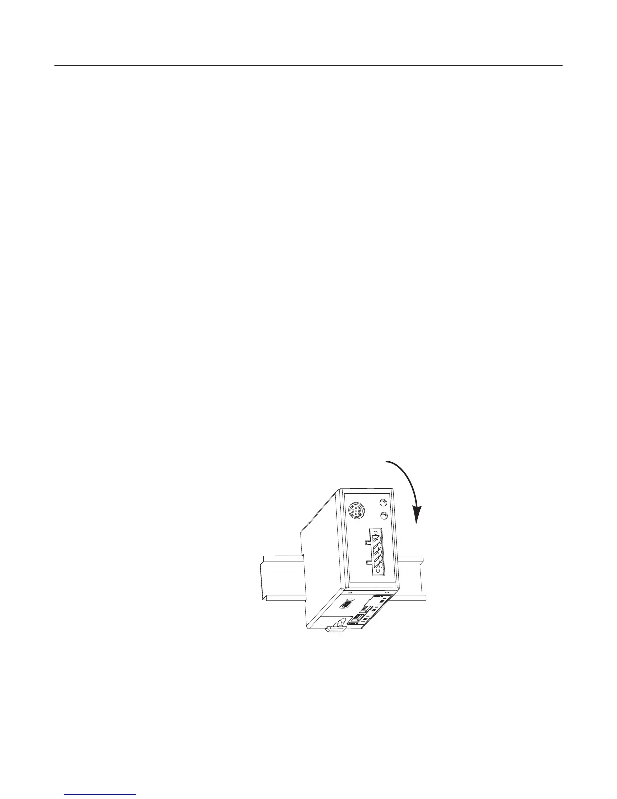
2. Hook the top lip of the module DIN rail mount onto the top of the
DIN rail and then rotate the module onto the DIN rail. You will
hear the module snap into a locked position.
Figure 3.2
Mounting the Module onto the DIN Rail
AB0940
efesotomasyon.com - Allen Bradley,Rockwell,plc,servo,drive
 Loading...


