Rockwell Automation Publication 2099-UM001D-EN-P - December 2012 45
Kinetix 7000 Connector Data Chapter 3
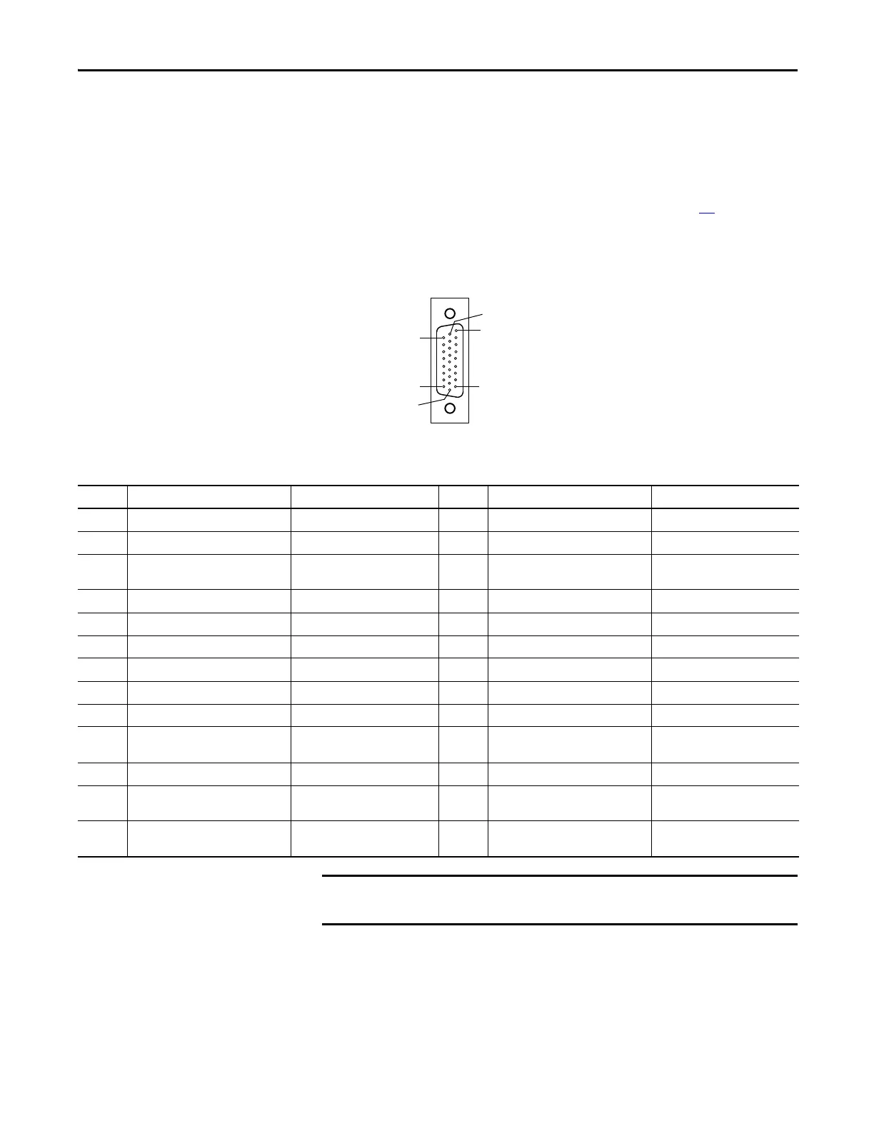
Digital and Analog Input/Output (IOD) Connector Pinout
The following diagram and table provide the signal description and pin-out
information for the 26-pin Digital and Analog Input/Output connector.
See Kinetix 7000 Front Panel Connectors and Displays on page 42
for the
location of the 26-pin connector. IOD signals are described in greater detail later
in this chapter.
Figure 20 - Pin Orientation for 26-pin I/O (IOD) Connector
Table 8 - Digital and Analog Input/Output 26-pin (IOD) Connector
Pin 18
Pin 26
Pin 1
Pin 9
Pin 10
Pin 19
Pin Description Signal Name Pin Description Signal Name
1 Drive supplied +24V DC HW_Enable_Pwr 14 Registration 1 Input Reg_1_In
2 Hardware Enable Switch Input HW_Enable_In 15 Registration 1 Common Reg_1_Com
3 Hardware Enable Common HW_Enable_Com 16 Drive supplied Registration 2 Output
Power
Reg_2_Pwr
4 Drive supplied +24V DC Home_Switch_Pwr 17 Registration 2 Input Reg_2_In
5 Home Switch Input Home_Switch_In 18 Registration 2 Common Reg_2_Com
6 Home Common Home_Switch_Com 19 Differential Analog Channel 1 Input Analog_Input_1
7 Drive supplied +24V DC Pos_OverTravel_Pwr 20 Differential Analog Channel 1 Common Analog_Input_1_Ret
8 Positive Overtravel Limit Switch Input Pos_ OverTravel_In 21 Differential Analog Channel 2 Input Analog_Input_2
9 Positive Overtravel Common Pos_OverTravel_Com 22 Differential Analog Channel 2 Common Analog_Input_2_Ret
10 Drive supplied +24V DC Neg_OverTravel_Pwr 23 Programmable Analog Channel 1
Output
Analog_Out_1
11 Negative Overtravel Limit Switch Input Neg_OverTravel_In 24 Analog Channel 1 Common Analog_Out_1_Ret
12 Negative Overtravel Common Neg_OverTravel_Com 25 Programmable Analog Channel 2
Output
Analog_Out_2
13 Drive supplied Registration 1 Output
Power
Reg_1_Pwr 26 Analog Channel 2 Common Analog_Out_2_Ret
The Drive supplied +24V DC and Common source signals (at pins 1, 3, 4, 6,
7, 9, 10, and 12) can only be used for the inputs listed above.

 Loading...


