Rockwell Automation Publication 2099-UM001D-EN-P - December 2012 47
Kinetix 7000 Connector Data Chapter 3
Motor Feedback (MF) Connector Pinouts
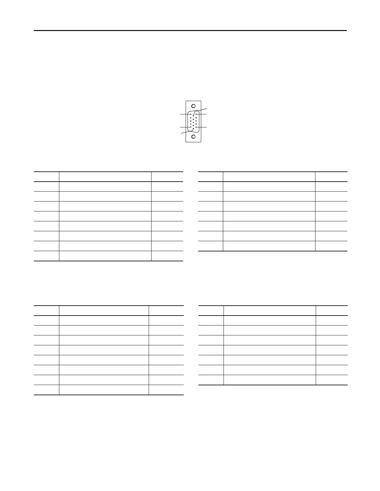
The following diagram and tables provide the orientation and signal description
for the Motor Feedback (MF) connector for each applicable feedback device.
Figure 23 - Pin Orientation for 15-pin Motor Feedback (MF) Connector
Table 11 - Motor Feedback (MF) Connections for Stegmann Hiperface (SRS/SRM)
Table 12 - Motor Feedback (MF) Connections for TTL or Sine/Cosine with Index Pulse and Hall
Commutation
Pin 11
Pin 6
Pin 15
Pin 1
Pin 10
Pin 5
Pin Description Signal Pin Description Signal
1 Sine differential input+ SIN+ 9 Reserved —
2 Sine differential input- SIN- 10 Hiperface data channel DATA-
3 Cosine differential input+ COS+ 11 Motor thermal switch (normally-closed)
(1)
TS
4 Cosine differential input- COS- 12 Reserved —
5 Hiperface data channel DATA+ 13 Reserved —
6 Common ECOM 14 Encoder power (+5V) EPWR_5V
(2)
7 Encoder power (+9V) EPWR_9V
(2)
15 Reserved —
8Reserved —
(1) Not applicable unless the motor has integrated thermal protection.
(2) Encoder power supply uses either 5V or 9V DC based on encoder/motor used.
Pin Description Signal Pin Description Signal
1 AM+ / Sine differential input+ AM+ / SIN+ 9 Reserved —
2 AM- / Sine differential input- AM- / SIN- 10 Index pulse- IM-
3 BM+ / Cosine differential input+ BM+ / COS+ 11 Motor thermal switch (normally-closed)
(1)
TS
4 BM- / Cosine differential input- BM- / COS- 12 Single-ended 5V hall effect commutation S1
5 Index pulse+ IM+ 13 Single-ended 5V hall effect commutation S2
6 Common ECOM 14 Encoder power (+5V) EPWR_5V
(2)
7 Encoder power (+9V) EPWR_9V
(2)
15 Reserved —
8 Single-ended 5V hall effect commutation S3
(1) Not applicable unless motor has integrated thermal protection.
(2) Encoder power supply uses either 5V or 9V DC based on encoder/motor used.

 Loading...


