78 Rockwell Automation Publication 2099-UM001D-EN-P - December 2012
Chapter 4 Connect the Kinetix 7000 Drive System
Setting the Ground Jumper
in Ungrounded Power
Configurations
To disconnect the ground reference for Kinetix 7000 drives in an ungrounded,
impedance grounded, high-resistive grounded, B-phase grounded, or common
DC bus power distribution system, remove the jumpers or wires as instructed in
the following table.
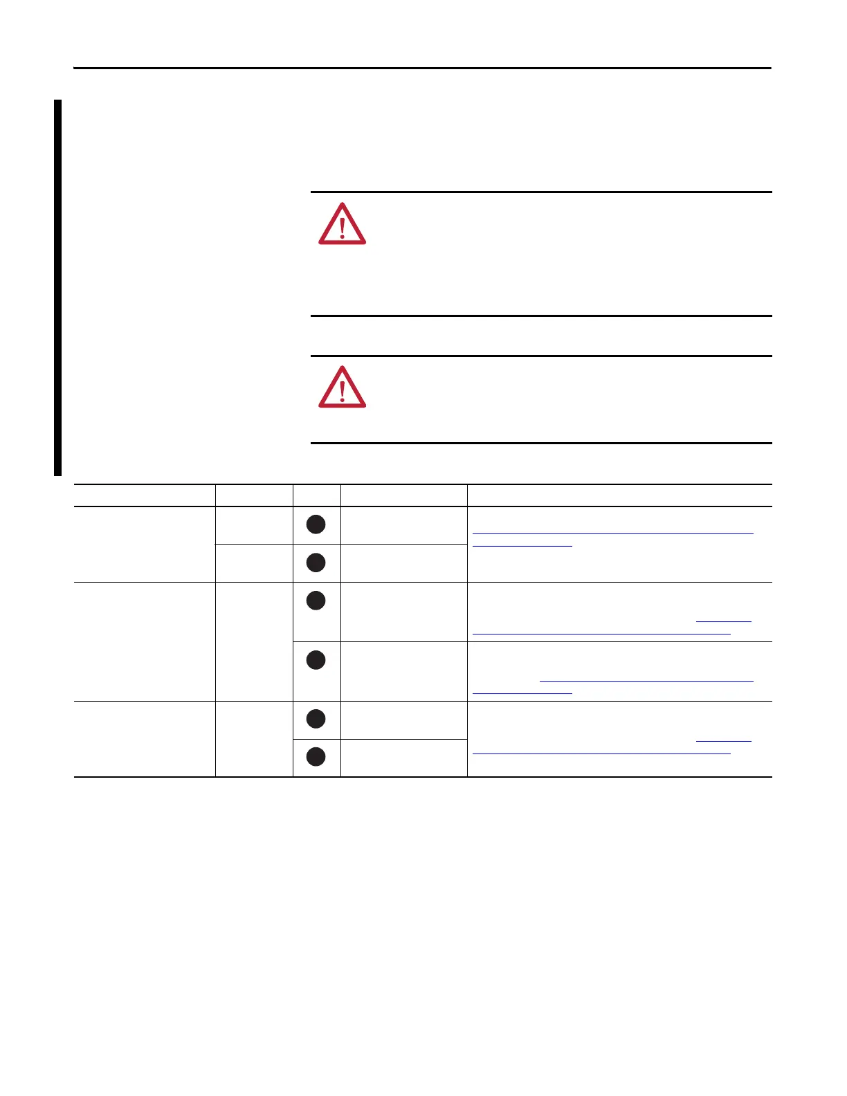
Table 31 - Jumper/Wire Location and Removal Instructions
ATTENTION: Kinetix 7000 drives contain protective metal oxide varistors
(MOVs) and common mode capacitors that are referenced to ground. In a
grounded power distribution system, these devices assist in isolating the drive
from electromagnetic interference (EMI).
These devices must be disconnected if the drive is installed in an ungrounded,
unbalanced, impedance grounded, or common DC bus power distribution system.
ATTENTION: To avoid an electrical shock, verify that the voltage on the bus
capacitors has discharged before removing or installing jumpers.
Measure the DC bus voltage at the DC+ and DC- terminals on the power terminals.
The voltage must be zero.
Drive Jumper/Wire ID No. Component Location
2099-BM06-S, 2099-BM07-S and
2099-BM08-S
PEA Common mode capacitor Remove the two jumpers located above the power terminal block. See
Removing the Ground Jumper on 2099-BM06-S, 2099-BM07-S, and 2099-
BM08-S Drives on page 79.
PEB MOVs
2099-BM09-S and
2099-BM10-S
Green/yellow
wire
Common mode capacitor Remove DC-DC converter and drive top cover, and disconnect the green/
yellow wire from the drive chassis. Insulate and secure the wire to prevent
unintentional contact with the chassis or components. See Removing the
Ground Wires on 2099-BM09-S and 2099-BM10-S Drives on page 80.
MOVs/input filter cap Disconnect the green/yellow wire next to the power terminal block. Insulate
and secure the wire to prevent unintentional contact with the chassis or
components. See Removing the Ground Wires on 2099-BM09-S and 2099-
BM10-S Drives on page 80.
2099-BM11-S and
2099-BM12-S
Green/yellow
wire
Common mode capacitor Disconnect the two green/yellow wires from the PE terminals on the power
terminal block. Insulate and secure each of these wires to prevent
unintentional contact with the chassis or components. See Removing the
Ground Wires on 2099-BM11-S and 2099-BM12-S Drives on page 80.
MOVs
1
2
3
4
5
6

 Loading...


