Rockwell Automation Publication 2099-UM001D-EN-P - December 2012 55
Kinetix 7000 Connector Data Chapter 3
Hardware Enable
The Hardware Enable input is an optically isolated (500V), single-ended, active
high signal. A 24V DC input applied to this pin enables the drive.
The status of this digital input can be monitored in the axis servo drive tag in
RSLogix.
If the Drive Hardware Enable option is selected in Logix, an MSO (Motion
Servo On) instruction must be executed in RSLogix software. This causes IOD-1
to supply 24V DC to IOD-2, and completes the enable circuit for servo loop and
drive power structure.
If the Drive Hardware Enable option is not selected in Logix, an MSO
instruction will enable the drive without the need for a Drive Enable signal
confirmation.
This input is level sensitive. See Table 1 9
- Digital Input Descriptions and
Tab l e 20
- Digital Input Specifications starting on page 54 for On/Off signal
voltages and current levels.
Kinetix 7000 drive Hardware Enable functions and faults actions are
programmed through RSLogix software. Kinetix 7000 dive firmware provides an
additional 50 ms of debounce.
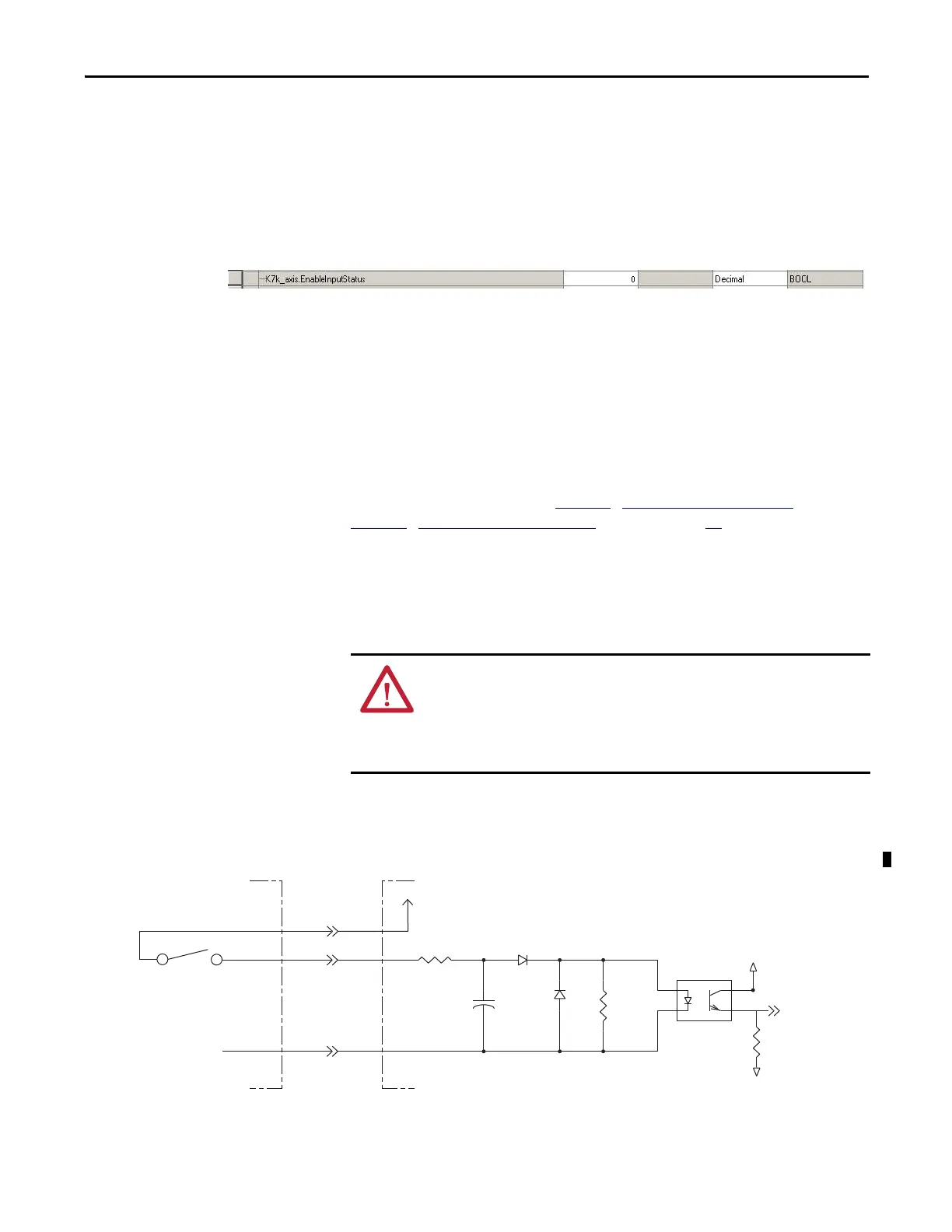
The schematic below depicts the Hardware Enable circuit. It is provided as a
reference only.
Figure 31 - Hardware Enable Digital Input Circuit Diagram
(1) +24V DC source (range) = 21.6V…26.4V (supplied by the drive, not to exceed 300 mA total).
Maximum current input = 10 mA.
ATTENTION: Overvoltage protection is not provided for the Hardware Enable
input signal.
It is recommended to use the on-drive power to power the Hardware Enable signal.
If an external power source is used, you must take responsibility to be sure that the
voltage/current does not exceed the rating of the input.
2k Ω
0.1 μF
511 Ω
VCC
INPUT
IO_COM
I/O SUPPLY
1k Ω
Kinetix 7000 DriveCustomer-supplied Input Device
+24V DC
(1)
CTRL_INPUT
IOD-1
IOD-3
IOD-2

 Loading...


