162 Rockwell Automation Publication 2080-UM005B-EN-E - March 2015
Appendix D IPID Function Block
PID Application Example
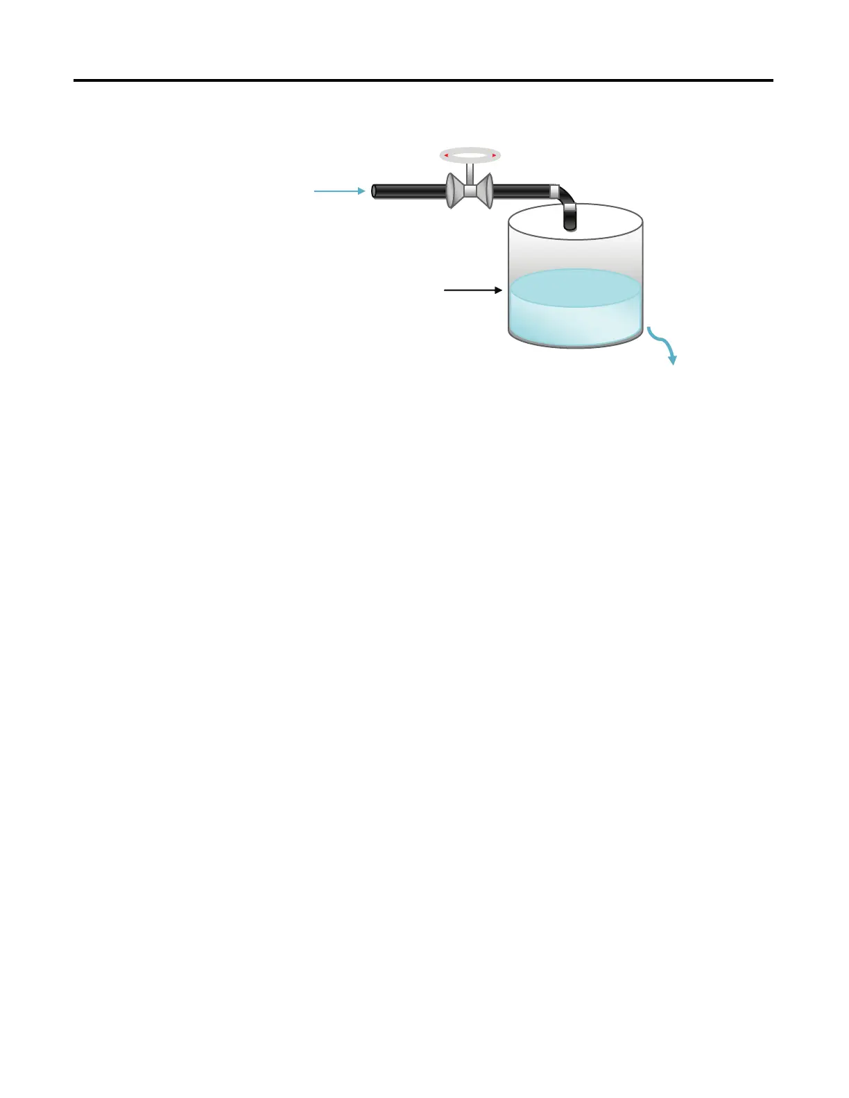
The illustration above shows a basic water level control system, to maintain a
preset water level in the tank. A solenoid valve is used to control incoming water,
filling the tank at a preset rate. Similarly, outflowing water is controlled at a
measureable rate.
IPID Autotuning for First and Second Order Systems
Autotune of IPID can only work on first and second order systems.
A first order system can be described by a single independent energy storage
element. Examples of first order systems are the cooling of a fluid tank, the flow of
fluid from a tank, a motor with constant torque driving a disk flywheel or an
electric RC lead network. The energy storage element for these systems are heat
energy, potential energy, rotational kinetic energy and capacitive storage energy,
respectively.
This may be written in a standard form such as f(t) = τdy/dt + y(t), where τ is the
system time constant, f is the forcing function and y is the system state variable.
In the cooling of a fluid tank example, it can be modeled by the thermal
capacitance C of the fluid and thermal resistance R of the walls of the tank. The
system time constant will be RC, the forcing function will be the ambient
temperature and the system state variable will be the fluid temperature.
A second order system can be described by two independent energy storage
elements which exchange stored energy. Examples of second order systems are a
motor driving a disk flywheel with the motor coupled to the flywheel via a shaft
with torsional stiffness or an electric circuit composed of a current source driving
a series LR (inductor and resistor) with a shunt C (capacitor). The energy storage
elements for these systems are the rotational kinetic energy and torsion spring
energy for the former and the inductive and capacitive storage energy for the
latter. Motor drive systems and heating systems can be typically modeled by the
LR and C electric circuit.
Water In
Water Level
Tank
Water Out

 Loading...


