30 Rockwell Automation Publication 2080-UM005B-EN-E - March 2015
Chapter 4 Wire Your Controller
• Separate wiring by signal type. Bundle wiring with similar electrical
characteristics together.
• Separate input wiring from output wiring.
• Label wiring to all devices in the system. Use tape, shrink-tubing, or other
dependable means for labeling purposes. In addition to labeling, use
colored insulation to identify wiring based on signal characteristics. For
example, you may use blue for DC wiring and red for AC wiring.
Wire Requirements
Use Surge Suppressors
Because of the potentially high current surges that occur when switching
inductive load devices, such as motor starters and solenoids, the use of some type
of surge suppression to protect and extend the operating life of the controllers
output contacts is required. Switching inductive loads without surge suppression
can significantly reduce the life expectancy of relay contacts. By adding a
suppression device directly across the coil of an inductive device, you prolong the
life of the output or relay contacts. You also reduce the effects of voltage
transients and electrical noise from radiating into adjacent systems.
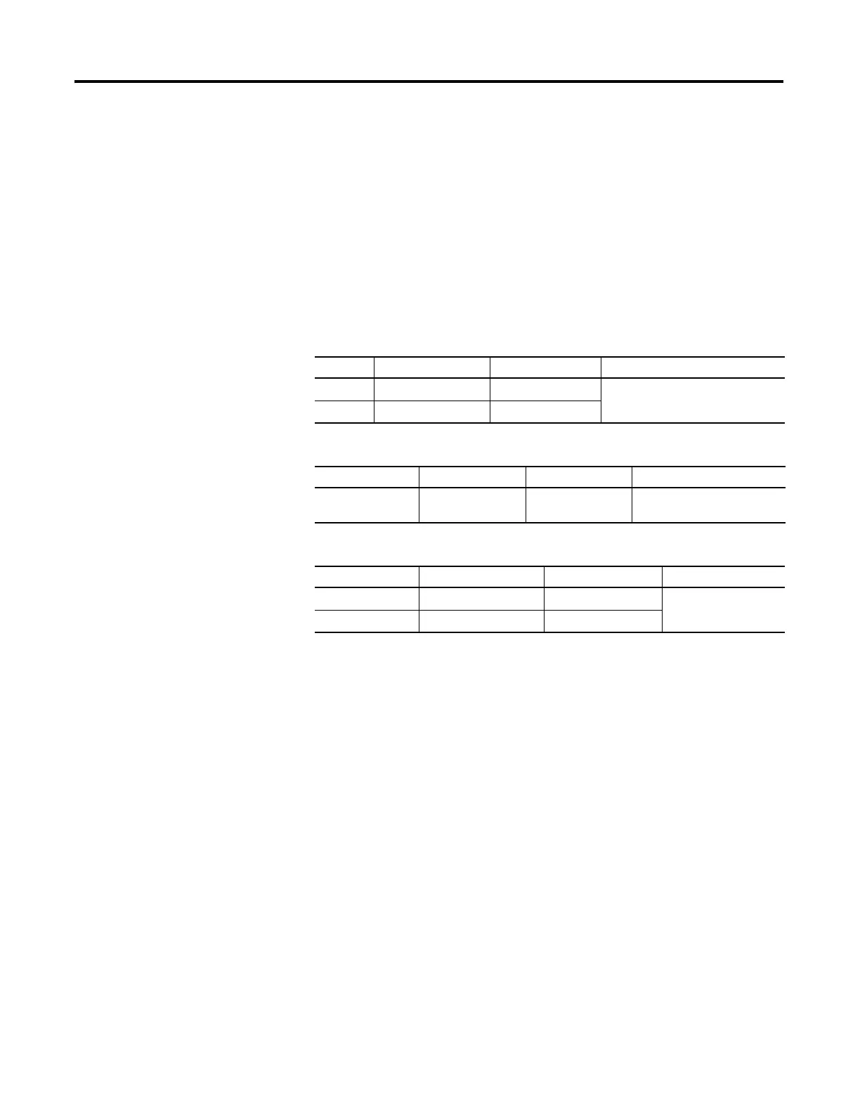
Wire Requirements for fixed terminal blocks
Min Max
Solid 0.14 mm
2
(26 AWG) 2.5 mm
2
(14 AWG) rated @ 90 °C (194 °F ) insulation
max
Stranded 0.14 mm
2
(26 AWG) 1.5 mm
2
(16 AWG)
Wire requirements for removable terminal blocks
Min Max
Solid and Stranded 0.2 mm
2
(24 AWG) 2.5 mm
2
(14 AWG) rated @ 90 °C (194 °F )
insulation max
Wire requirements for RS232/RS485 serial port terminal block
Min Max
Solid 0.14 mm
2
(26 AWG) 1.5 mm
2
(16 AWG) rated @ 90 °C (194 °F)
insulation max
Stranded 0.14 mm
2
(26 AWG) 1.0 mm
2
(18 AWG)

 Loading...


