122 Rockwell Automation Publication 2711P-UM006E-EN-P - January 2017
Chapter 5 Install and Replace Components
2. If the display module is removed from the panel, set the terminal, display-
side down, on a clean, flat, stable surface.
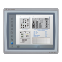
3. Position the communication module over the logic module so that the
connector on the bottom of the module aligns with the connector on the
logic module.
4. To prevent ESD between the modules, let the communication module
touch the logic module before making the connection.
5. Push down on the communication module until the connectors are seated.
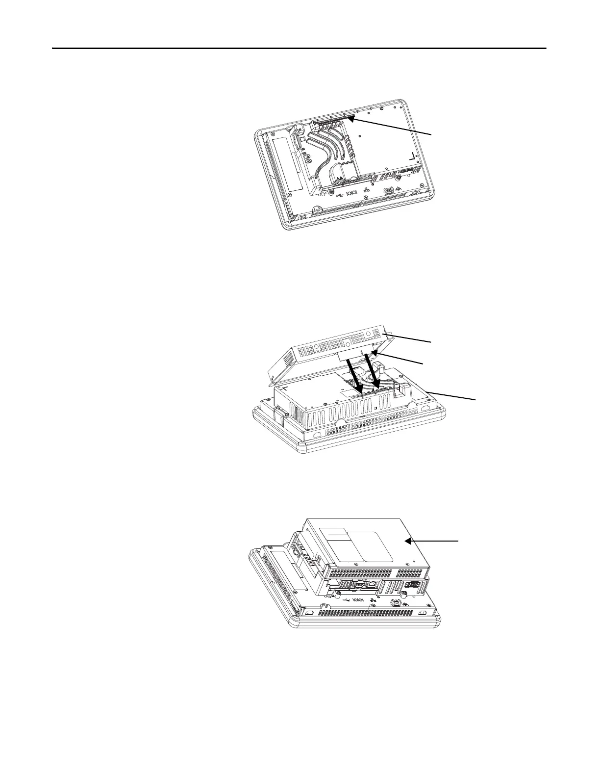
6. Tighten the four screws that secure the communication module to the
logic module to a torque of 0.58 N•m (5…7 lb•in).
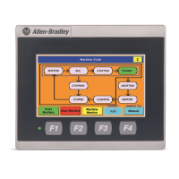
Connector for
Communication Module
Communication
Connector
Logic Module
Attached
Communication Module

 Loading...