124 Rockwell Automation Publication 2711P-UM006E-EN-P - January 2017
Chapter 5 Install and Replace Components
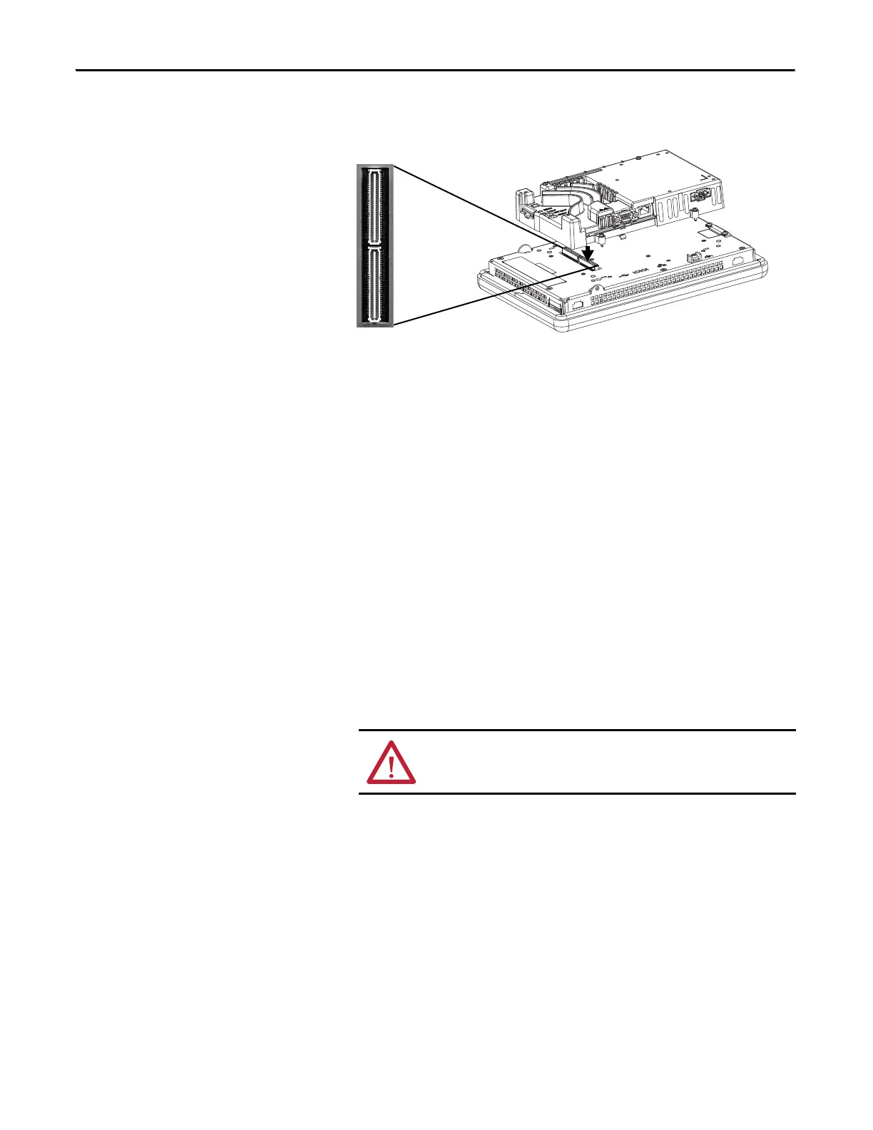
7. Position the logic module over the new display module so that the
connectors align.
8. Push down on the logic module until firmly seated.
9. Tighten the four captive secures that secure the logic module to the display
module and torque to 0.58 N•m (5…7 lb•in).
10. Attach the communication module, if necessary, and torque the four
screws to 0.58 N•m (5…7 lb•in).
Replace the Bezel
You can replace the bezel on the 700, 1000, 1250, and 1500 terminals. It is not
necessary to remove the logic module or communication module before
removing the bezel, except on the 700 terminal.
Remove the Display Module Bezel
Follow these steps to remove the display module bezel.
1. Disconnect power from the terminal.
2. Set the terminal, display side down, on a flat stable surface.
3. On touch-screen only terminals, remove the two screws that secure the
small metal plate to the back of the display module.
ATTENTION: Wear a properly grounded ESD wristband before touching
any of the electronic components in the logic module.

 Loading...